MOD.MASTER.W/ETEXT ENG.MECHANICS CARD+BK
15th Edition
ISBN: 9780137519170
Author: HIBBELER
Publisher: PEARSON
expand_more
expand_more
format_list_bulleted
Videos
Textbook Question
Chapter 7, Problem 112P
The cable will break when the maximum tension reaches T max = 10 kN. Determine the minimum sag h if it supports the uniform distributed load of w = 600 N/m.
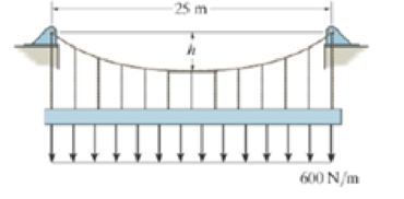
Prob. 7–112
Expert Solution & Answer
Want to see the full answer?
Check out a sample textbook solution
Students have asked these similar questions
explain how to find the resultant internal
loading acting on the cross section at point A. Draw all
necessary free-body diagrams and indicate the relevant
equations of equilibrium. Do not calculate values The lettered
dimensions, angles, and loads are assumed to be known.
P7-1.
м
в
-a/2--/2-
explain how to find the resultant internal
loading acting on the cross section at point A. Draw all
necessary free-body diagrams, and indicate the relevant
equations of equilibrium. Do not calculate values The lettered
dimensions, angles, and loads are assumed to be known.
P7-1.
The bent bar is supported by smooth journal bearings at A, B and C and is subjected to couple
moment of 200 N.m. Determine the support reaction at each of the smooth journal bearings.
200 N.m
/0.4 m/
B
0.7 m
0.6 m
Figure 2
Chapter 7 Solutions
MOD.MASTER.W/ETEXT ENG.MECHANICS CARD+BK
Ch. 7 - Determine the normal force, shear force, and...Ch. 7 - Determine the normal force, shear force, and...Ch. 7 - Determine the normal force, shear force, and...Ch. 7 - Determine the normal force, shear force, and...Ch. 7 - Determine the normal force, shear force, and...Ch. 7 - Determine the normal force, shear force, and...Ch. 7 - Determine the shear force and moment at points C...Ch. 7 - The pliers are used to grip the tube at B. If a...Ch. 7 - Determine the distance a as a fraction of the...Ch. 7 - The cable will fail when subjected to a tension of...
Ch. 7 - Determine the distance a between the bearings in...Ch. 7 - The cantilevered rack is used to support each end...Ch. 7 - Rod AB is fixed to a smooth collar D, which slides...Ch. 7 - Prob. 22PCh. 7 - Determine the normal force, shear force, and...Ch. 7 - The distributed loading W = W0 sin , measured per...Ch. 7 - Solve Prob. 7-39 for = 120. Probs. 739/40Ch. 7 - Determine the x, y, z components of force and...Ch. 7 - Determine the x, y, z components of internal...Ch. 7 - Determine the shear and moment as a function of x,...Ch. 7 - Determine the shear and moment as a function of x,...Ch. 7 - Determine the shear and moment as a function of x,...Ch. 7 - Determine the shear and moment as a function of x,...Ch. 7 - Determine the shear and moment as a function of x,...Ch. 7 - Determine the shear and moment as a function of x,...Ch. 7 - Draw the shear and moment diagrams for the shaft...Ch. 7 - Draw the shear and moment diagrams for the beam...Ch. 7 - Draw the shear and moment diagrams for the beam...Ch. 7 - Draw the shear and moment diagrams for the...Ch. 7 - Draw the shear and moment diagrams of the beam (a)...Ch. 7 - If L = 9 m, the beam will fail when the maximum...Ch. 7 - Draw the shear and moment diagrams for the beam....Ch. 7 - Draw the shear and moment diagrams for the beam....Ch. 7 - The shaft is supported by a smooth thrust bearing...Ch. 7 - Draw the shear and moment diagrams for the beam....Ch. 7 - Prob. 58PCh. 7 - Prob. 59PCh. 7 - The shaft is supported by a smooth thrust bearing...Ch. 7 - Draw the shear and moment diagrams for the beam....Ch. 7 - Prob. 65PCh. 7 - Draw the shear and moment diagrams for the beam....Ch. 7 - Draw the shear and moment diagrams for the beam....Ch. 7 - Draw the shear and moment diagrams for the beam....Ch. 7 - Draw the shear and moment diagrams for the beam....Ch. 7 - Draw the shear and moment diagrams for the beam....Ch. 7 - Draw the shear and moment diagrams for the beam....Ch. 7 - Draw the shear and moment diagrams for the beam....Ch. 7 - Draw the shear and moment diagrams for the beam....Ch. 7 - Draw the shear and moment diagrams for the beam....Ch. 7 - Draw the shear and moment diagrams for the beam....Ch. 7 - Draw the shear and moment diagrams for the beam....Ch. 7 - Draw the shear and moment diagrams for the beam....Ch. 7 - Draw the shear and moment diagrams for the beam....Ch. 7 - The cable supports the three loads shown....Ch. 7 - Prob. 95PCh. 7 - Determine the tension in each segment of the cable...Ch. 7 - Prob. 97PCh. 7 - The cable supports the loading shown. Determine...Ch. 7 - The cable supports the three loads shown....Ch. 7 - The cable supports the three loads shown....Ch. 7 - Determine the maximum uniform loading w, measured...Ch. 7 - The cable is subjected to a uniform loading of w =...Ch. 7 - If x = 2 ft and the crate weighs 300 lb, which...Ch. 7 - If yB = 1.5 ft. determine the largest weight of...Ch. 7 - The cable supports a girder which weighs 850...Ch. 7 - If the pipe has a mass per unit length of 1500...Ch. 7 - Prob. 110PCh. 7 - The cable will break when the maximum tension...Ch. 7 - Prob. 2RPCh. 7 - Prob. 3RPCh. 7 - Prob. 4RPCh. 7 - Draw the shear and moment diagrams for the beam....Ch. 7 - A chain is suspended between points at the same...
Knowledge Booster


Learn more about
Need a deep-dive on the concept behind this application? Look no further. Learn more about this topic, mechanical-engineering and related others by exploring similar questions and additional content below.Similar questions
- The link AB of the pliers has the cross section dimensions 3mm x 20mm, and is made of steel with elastic modulus E= 190 GPa. Determine the value of the force F that would cause failure of the link by bucklingarrow_forwardexplain how to find the resultant internal loading acting on the cross section at point A. Draw all necessary free-body diagrams, and indicate the relevant equations of equilibrium. Do not calculate values The lettered dimensions, angles, and loads are assumed to be known. P7-1. вarrow_forwardThe truss is supported by a pin at A and a roller at B. Determine the support reactions. The truss is supported by a pin at A and a roller at B. Determine the support reactions. 0.1N kN -2 m- 4 m 2 m P kN 4 m 450 P = 5 N = 100arrow_forward
- The horizontal beam is assumed to be rigid and supports the distributed load shown. Determine the vertical reactions at the supports. Each support consists of a wooden post having a diameter of 120 mm and an unloaded (original) length of 1.40 m. Take E = 12 GPa. The horizontal beam is assumed to be rigid and supports the distributed load shown. Determine the angle of tilt of the beam after the load is applied. Each support consists of a wooden post having a diameter of 120 mm and an unloaded (original) length of 1.40 m. Take Ew = 12 GPa. 18 kN/m A 1.40 m 2 m +1m-arrow_forwardThe boom DF at the job crane and the column DE have a uniform weight of sw N/m. If the hoist and load weight P N, determine the resultant internal loading in the crane on cross-section through points A, B and C. h2 L1=1 m L2=2 m L3=1 m h1=1 m h2=1.3 m h1 P=540 N Sw=18 N/m D E B L1 L2 A L3 P Farrow_forwardR9-7. The rigid link is supported by a pin at A and two A-36 steel wires, each having an unstretched length of 300 mm and cross-sectional area of Z8 mm. Determine the force developed in the wires when the link supports the vertical load of 1.75 kN. -300 mm- 125 mim 100 -150 mm 1.75 kNarrow_forward
- The rigid beam is supported by a pin at C and an A-36 steel guy wire AB. If the wire has a diameter of 0.2 in., determine how much it stretches when a distributed load of w = 100 lb>ft acts on the beam. The material remains elastic.arrow_forwardDetermine the forces in members CD, CJ, and DJ. 6 panels at 3¹ K I DAN C D E L L M 6' A L B L L H F G L Larrow_forwardThe way to the column where the loading status is seen determine the P load required for the 5 mm horizontal displacement of the C midpoint and the maximum shear stress that this P load will generate. b=750mm a=50mm t=4mm e=48mm E(modulus of elasticity)=70GPAarrow_forward
- The rigid beam is supported by three 25-mm diameters A-36 steel rods. If the beam supports the force of P = 230 kN, determine the force developed in each rod. Consider the steel to be an elastic perfectly plastic material.arrow_forwardDetermine the force in each member of the loaded truss. The force is positive if in tension, negative if in compression. Answers: AB= AC = 62° 15° i 1.19 BC= i i 1.96 -0.957 39° W B W W Warrow_forwardThe pipe with two rigid caps attached to its ends is subjected to an axial force P. If the pipe is made from a material having a modulus of elasticity E and Poisson’s ratio n, determine the change in volume of the material.arrow_forward
arrow_back_ios
SEE MORE QUESTIONS
arrow_forward_ios
Recommended textbooks for you
 Elements Of ElectromagneticsMechanical EngineeringISBN:9780190698614Author:Sadiku, Matthew N. O.Publisher:Oxford University Press
 Mechanics of Materials (10th Edition)Mechanical EngineeringISBN:9780134319650Author:Russell C. HibbelerPublisher:PEARSON
 Thermodynamics: An Engineering ApproachMechanical EngineeringISBN:9781259822674Author:Yunus A. Cengel Dr., Michael A. BolesPublisher:McGraw-Hill Education
 Control Systems EngineeringMechanical EngineeringISBN:9781118170519Author:Norman S. NisePublisher:WILEY
 Mechanics of Materials (MindTap Course List)Mechanical EngineeringISBN:9781337093347Author:Barry J. Goodno, James M. GerePublisher:Cengage Learning
 Engineering Mechanics: StaticsMechanical EngineeringISBN:9781118807330Author:James L. Meriam, L. G. Kraige, J. N. BoltonPublisher:WILEY
Elements Of Electromagnetics
Mechanical Engineering
ISBN:9780190698614
Author:Sadiku, Matthew N. O.
Publisher:Oxford University Press
Mechanics of Materials (10th Edition)
Mechanical Engineering
ISBN:9780134319650
Author:Russell C. Hibbeler
Publisher:PEARSON
Thermodynamics: An Engineering Approach
Mechanical Engineering
ISBN:9781259822674
Author:Yunus A. Cengel Dr., Michael A. Boles
Publisher:McGraw-Hill Education
Control Systems Engineering
Mechanical Engineering
ISBN:9781118170519
Author:Norman S. Nise
Publisher:WILEY
Mechanics of Materials (MindTap Course List)
Mechanical Engineering
ISBN:9781337093347
Author:Barry J. Goodno, James M. Gere
Publisher:Cengage Learning
Engineering Mechanics: Statics
Mechanical Engineering
ISBN:9781118807330
Author:James L. Meriam, L. G. Kraige, J. N. Bolton
Publisher:WILEY
Mechanical SPRING DESIGN Strategy and Restrictions in Under 15 Minutes!; Author: Less Boring Lectures;https://www.youtube.com/watch?v=dsWQrzfQt3s;License: Standard Youtube License