MOD.MASTER.W/ETEXT ENG.MECHANICS CARD+BK
15th Edition
ISBN: 9780137519170
Author: HIBBELER
Publisher: PEARSON
expand_more
expand_more
format_list_bulleted
Concept explainers
Videos
Textbook Question
Chapter 7, Problem 98P
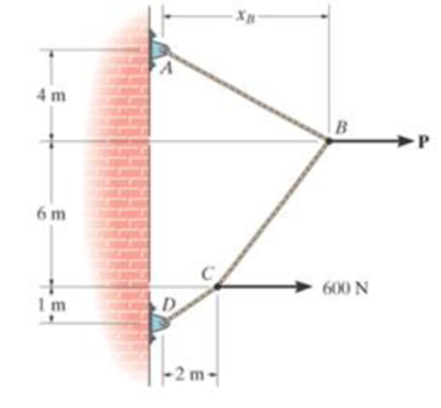
The cable supports the loading shown. Determine the magnitude of the horizontal force P so that xB = 5 m.
Probs. 7–97/98
Expert Solution & Answer
Want to see the full answer?
Check out a sample textbook solution
Students have asked these similar questions
Problem 4
The cable of a suspension bridge supports half of the uniform road surface
between the two towers at A and B, Fig. 7-21a. If this distributed loading is
0,, determine the maximum force developed in the cable and the cable's
required length. The span L and sag h are known.
Q1: The masthead fitting supports the two forces. Determine the magnitude of T which will cause no
bending of the mast (zero moment at point (C).
90
120
R7-1. Determine the internal normal force, shear force,
and moment at points D and E of the frame.
-3 ft
30°
E
8 ft
D
Prob. R7-1
C
1 ft
4 ft
150 lb
B
Chapter 7 Solutions
MOD.MASTER.W/ETEXT ENG.MECHANICS CARD+BK
Ch. 7 - Determine the normal force, shear force, and...Ch. 7 - Determine the normal force, shear force, and...Ch. 7 - Determine the normal force, shear force, and...Ch. 7 - Determine the normal force, shear force, and...Ch. 7 - Determine the normal force, shear force, and...Ch. 7 - Determine the normal force, shear force, and...Ch. 7 - Determine the shear force and moment at points C...Ch. 7 - The pliers are used to grip the tube at B. If a...Ch. 7 - Determine the distance a as a fraction of the...Ch. 7 - The cable will fail when subjected to a tension of...
Ch. 7 - Determine the distance a between the bearings in...Ch. 7 - The cantilevered rack is used to support each end...Ch. 7 - Rod AB is fixed to a smooth collar D, which slides...Ch. 7 - Prob. 22PCh. 7 - Determine the normal force, shear force, and...Ch. 7 - The distributed loading W = W0 sin , measured per...Ch. 7 - Solve Prob. 7-39 for = 120. Probs. 739/40Ch. 7 - Determine the x, y, z components of force and...Ch. 7 - Determine the x, y, z components of internal...Ch. 7 - Determine the shear and moment as a function of x,...Ch. 7 - Determine the shear and moment as a function of x,...Ch. 7 - Determine the shear and moment as a function of x,...Ch. 7 - Determine the shear and moment as a function of x,...Ch. 7 - Determine the shear and moment as a function of x,...Ch. 7 - Determine the shear and moment as a function of x,...Ch. 7 - Draw the shear and moment diagrams for the shaft...Ch. 7 - Draw the shear and moment diagrams for the beam...Ch. 7 - Draw the shear and moment diagrams for the beam...Ch. 7 - Draw the shear and moment diagrams for the...Ch. 7 - Draw the shear and moment diagrams of the beam (a)...Ch. 7 - If L = 9 m, the beam will fail when the maximum...Ch. 7 - Draw the shear and moment diagrams for the beam....Ch. 7 - Draw the shear and moment diagrams for the beam....Ch. 7 - The shaft is supported by a smooth thrust bearing...Ch. 7 - Draw the shear and moment diagrams for the beam....Ch. 7 - Prob. 58PCh. 7 - Prob. 59PCh. 7 - The shaft is supported by a smooth thrust bearing...Ch. 7 - Draw the shear and moment diagrams for the beam....Ch. 7 - Prob. 65PCh. 7 - Draw the shear and moment diagrams for the beam....Ch. 7 - Draw the shear and moment diagrams for the beam....Ch. 7 - Draw the shear and moment diagrams for the beam....Ch. 7 - Draw the shear and moment diagrams for the beam....Ch. 7 - Draw the shear and moment diagrams for the beam....Ch. 7 - Draw the shear and moment diagrams for the beam....Ch. 7 - Draw the shear and moment diagrams for the beam....Ch. 7 - Draw the shear and moment diagrams for the beam....Ch. 7 - Draw the shear and moment diagrams for the beam....Ch. 7 - Draw the shear and moment diagrams for the beam....Ch. 7 - Draw the shear and moment diagrams for the beam....Ch. 7 - Draw the shear and moment diagrams for the beam....Ch. 7 - Draw the shear and moment diagrams for the beam....Ch. 7 - The cable supports the three loads shown....Ch. 7 - Prob. 95PCh. 7 - Determine the tension in each segment of the cable...Ch. 7 - Prob. 97PCh. 7 - The cable supports the loading shown. Determine...Ch. 7 - The cable supports the three loads shown....Ch. 7 - The cable supports the three loads shown....Ch. 7 - Determine the maximum uniform loading w, measured...Ch. 7 - The cable is subjected to a uniform loading of w =...Ch. 7 - If x = 2 ft and the crate weighs 300 lb, which...Ch. 7 - If yB = 1.5 ft. determine the largest weight of...Ch. 7 - The cable supports a girder which weighs 850...Ch. 7 - If the pipe has a mass per unit length of 1500...Ch. 7 - Prob. 110PCh. 7 - The cable will break when the maximum tension...Ch. 7 - Prob. 2RPCh. 7 - Prob. 3RPCh. 7 - Prob. 4RPCh. 7 - Draw the shear and moment diagrams for the beam....Ch. 7 - A chain is suspended between points at the same...
Knowledge Booster


Learn more about
Need a deep-dive on the concept behind this application? Look no further. Learn more about this topic, mechanical-engineering and related others by exploring similar questions and additional content below.Similar questions
- •7-13. Determine the internal normal force, shear force, and moment at point D of the two-member frame. 7-14. Determine the internal normal force, shear force, and moment at point E of the two-member frame. 250 N/m 2 m 15 m 300 N/m Probs. 7-13/14arrow_forwardThe beam is loaded with a uniformly varying load 0 at point D and maximum of 7 kN/m at the fixed support. Determine the tension in the cable. D B 0.8 m 1.8 m 0.4 m 25 kNarrow_forward*7-36. Determine the normal force, shear force, and moment acting at points B and C on the curved member. Problem 7-36 B 2 ft 45° 30° 3 500 lbarrow_forward
- The distributed load acts on the beam as shown. Determine the magnitude of the equivalent resultant force and specify where it acts measured from point A. w = (-2r2 + 4x + 16) Ib/ft A 4 ft -arrow_forwardThe cable of a suspension bridge supports half of the uniform road surfacebetween the two towers at A and B, Fig. 7-21a. If this distributed loading isω= 0 , determine the maximum force developed in the cable and the cable’srequired length. The span L and sag h are known.arrow_forwardNO 76% i 14:57 e MENG250 - Pract... 7 *2-96. The tower is held in place by three cables. If the force of each cable acting on the tower is shown, determine the magnitude and coordinate direction angles a, B, y of the resultant force. Take x = 20 m, y = 15 m. D. 600 N 400 N 80N 24 m 8 8 /9arrow_forward
- The bar of negligible weight is supported by two springs,each having a stiffness k = 80 N>m. If the springs are originally unstretched, and the force is vertical as shown,determine the angle theta the bar makes with the horizontal,when the 45-N force is applied to the bar. 1.5 m- 3 m C В 45 Narrow_forwardF7-2. Determine the internal normal force, shear force, and bending moment at point Cin the beam. 200 N/m 100 N/m 15m 1.5 m-arrow_forward4143. Replace this loading by an equivalent resultant force and specily its location, measured from point O. 6KNim 4 kN/m I!! 2m -15m- Prob. 4-143arrow_forward
- 7-98. The cable supports the loading shown. Determine the magnitude of the horizontal force P so that xg = 5 m. Problems 7-97/98 4 m 6 m 1 m Y D 2 m- XB B 600 Narrow_forwardDetermine the normal force, shear force, and moment at points D and E of the two-member frame. Note that while BC is pinned at both ends, it is not a 2-force member. 2 kN/m A 1.5 m D -1.5 m 1.5 m E 1.5 m B 1.5 kN/marrow_forwardThe slope of the 4.3 kN force F is specified as shown in the figure. Express F as a vector in terms of the unit vectors i and j. Assume a 13, b = 6. Answer: F = ( i a i+ j) KNarrow_forward
arrow_back_ios
SEE MORE QUESTIONS
arrow_forward_ios
Recommended textbooks for you
 Elements Of ElectromagneticsMechanical EngineeringISBN:9780190698614Author:Sadiku, Matthew N. O.Publisher:Oxford University Press
 Mechanics of Materials (10th Edition)Mechanical EngineeringISBN:9780134319650Author:Russell C. HibbelerPublisher:PEARSON
 Thermodynamics: An Engineering ApproachMechanical EngineeringISBN:9781259822674Author:Yunus A. Cengel Dr., Michael A. BolesPublisher:McGraw-Hill Education
 Control Systems EngineeringMechanical EngineeringISBN:9781118170519Author:Norman S. NisePublisher:WILEY
 Mechanics of Materials (MindTap Course List)Mechanical EngineeringISBN:9781337093347Author:Barry J. Goodno, James M. GerePublisher:Cengage Learning
 Engineering Mechanics: StaticsMechanical EngineeringISBN:9781118807330Author:James L. Meriam, L. G. Kraige, J. N. BoltonPublisher:WILEY
Elements Of Electromagnetics
Mechanical Engineering
ISBN:9780190698614
Author:Sadiku, Matthew N. O.
Publisher:Oxford University Press
Mechanics of Materials (10th Edition)
Mechanical Engineering
ISBN:9780134319650
Author:Russell C. Hibbeler
Publisher:PEARSON
Thermodynamics: An Engineering Approach
Mechanical Engineering
ISBN:9781259822674
Author:Yunus A. Cengel Dr., Michael A. Boles
Publisher:McGraw-Hill Education
Control Systems Engineering
Mechanical Engineering
ISBN:9781118170519
Author:Norman S. Nise
Publisher:WILEY
Mechanics of Materials (MindTap Course List)
Mechanical Engineering
ISBN:9781337093347
Author:Barry J. Goodno, James M. Gere
Publisher:Cengage Learning
Engineering Mechanics: Statics
Mechanical Engineering
ISBN:9781118807330
Author:James L. Meriam, L. G. Kraige, J. N. Bolton
Publisher:WILEY
Types Of loads - Engineering Mechanics | Abhishek Explained; Author: Prime Course;https://www.youtube.com/watch?v=4JVoL9wb5yM;License: Standard YouTube License, CC-BY