
Concept explainers
Videos
In the circuit of Fig. 7.93,
- (a) Find R, L, and τ.
- (b) Calculate the energy dissipated in the resistance for 0 < t < 0.5 ms.
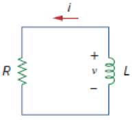
Figure 7.93
For Prob. 7.13.
(a)
Find the value of resistance R, inductance L and also find the time constant
Answer to Problem 13P
The value of resistance R in the circuit is
Explanation of Solution
Given data:
The voltage
The current
Formula used:
Write the general expression to find the voltage across the resistor using Ohms law.
Here,
Write the expression to find the time constant for RL circuit.
Here,
R is the resistance of the resistor, and
L is the inductance of the inductor.
Write the general expression to find the voltage response in the RL Circuit.
Here,
Calculation:
Substitute
Rearrange the above equation to find resistance R.
Compare the given voltage
Rearrange the equation (4) to find the time constant
Substitute
Rearrange the equation (5) to find the inductance L in Henry.
Conclusion:
Thus, the value of resistance R in the circuit is
(b)
Find the value of energy dissipated in the resistance for
Answer to Problem 13P
The value of energy dissipated in the resistance for
Explanation of Solution
Given data:
The energy dissipated in the resistance for the time limits
Formula used:
Write the expression to find the energy dissipated in the resistor.
Here,
Write the expression to find the power dissipated in the resistor.
Here,
Substitute equation (7) in equation (6) to find the energy dissipated in the resistor w.
Calculation:
Substitute
Rewrite the equation (9) as follows,
Reduce the equation (10) to find the energy dissipated in the resistor w in joules.
Converting the unit J to
Conclusion:
Thus, the value of energy dissipated in the resistance for
Want to see more full solutions like this?
Chapter 7 Solutions
EBK FUNDAMENTALS OF ELECTRIC CIRCUITS


- Problem 1 (time constant in RC Circuits, Alexander 7.2) 120 Ω 12Ω ww 50 V (+ 80 Ω 200 mF Figure P1 Find the time constant for the RC circuit in Figure P1. Hint: wouldn't the Thevenin transformation with respect to the capacitor terminals lead to the "standard" RC circuit? wwarrow_forwardProblem 1 (time constant in RC Circuits, Alexander 7.2) 120 Ω 12Ω ww 50 V (+ 80 Ω 200 mF Figure P1 Find the time constant for the RC circuit in Figure P1. wwarrow_forward7.11 For the circuit in Fig. 7.91, find i, for t > 0. t = 0 the 4 2 4 H ell LiThe time to rea 40 perce 24 V (+ 4Ω 82 18.T Sug Figure 7.91 For Prob. 7.11.arrow_forward
- 7.39 Calculate the capacitor voltage for t 0 for each of the circuits in Fig. 7.106. 20 V 12 V (4+1 402 www 2F +v- www 392 1+ V2F (a) 192 (b) засто 1=040 2Aarrow_forward7.14 Calculate the time constant of the circuit in Fig. 7.94. 20 ΚΩ www 40 ΚΩ ΑΛΛ Figure 7.94 For Prob. 7.14. 10 ΚΩ 5 mH ΑΛΜ 30 ΚΩarrow_forwardEXAMPLE 7. Find iL(t) for t> 0. Prior to closing switch @ t = 0. IL(0-) = 4 A, Vc(0-) = 15 V. %3D i(t) 4 A 20 H 20 Q 8 mF 20 Q ellarrow_forward
- The switch in Fig. 7.43 has been in position A for a long time. At t = 0, the switch moves to B. Determine v(t) for t > 0 and calculate its value at t = 1 s and 4 s. 24 V 3 ΚΩ ww 5kQ2 t=0 + B 4kQ M 0.5 mF 30 Varrow_forward10 Get Familiar with Inductors For the circuit in Fig. 7.100, and v = 90e-50t V i = 30e-50t A, t> 0 (a) Find L and R. (b) Determine the time constant. (c) Calculate the initial energy in the inductor. (d) What fraction of the initial energy is dissipated in 10 ms? R ww Figure 7.100 For Prob. 7.20. marrow_forwardIn the circuit of Fig. 7.67(a), determine the response v(t). t = 0 t = 0 + v(t) 12 Q H 0.1 F 30 V 6Ω 6Ω 3Ω 4) 4 A (a)arrow_forward
- The switch in Fig. 7.43 has been in position A for a long time. Att = 0, the switch moves to B. Determine (r) for r>0 and calculate its value at t = 1 s and 4 s. 24 V 3 k 310 A 8 05 F 30 Varrow_forwardIn the circuit shown in Fig. 7.81 v(t) = 56e-2001 V, t>0 - 200 %3D i(1) = 8e mA, t >0 (a) Find the values of R and C. (b) Calculate the time constant 7. (c) Determine the time required for the voltage to decay half its initial value at t = 0. R C Fig. 7.81 wwarrow_forwardComplete response RC 7.4. In the case of the following circuit, determine Vc(t) at t equal to: 0, 0+, and 0,008 s. 10u(t)V + 25 ΚΩ ww ve(t) + 5 μF 0.001 A 20 ΚΩ ww • 80 ΚΩarrow_forward
 Introductory Circuit Analysis (13th Edition)Electrical EngineeringISBN:9780133923605Author:Robert L. BoylestadPublisher:PEARSON
 Delmar's Standard Textbook Of ElectricityElectrical EngineeringISBN:9781337900348Author:Stephen L. HermanPublisher:Cengage Learning
 Programmable Logic ControllersElectrical EngineeringISBN:9780073373843Author:Frank D. PetruzellaPublisher:McGraw-Hill Education
 Fundamentals of Electric CircuitsElectrical EngineeringISBN:9780078028229Author:Charles K Alexander, Matthew SadikuPublisher:McGraw-Hill Education
 Electric Circuits. (11th Edition)Electrical EngineeringISBN:9780134746968Author:James W. Nilsson, Susan RiedelPublisher:PEARSON
 Engineering ElectromagneticsElectrical EngineeringISBN:9780078028151Author:Hayt, William H. (william Hart), Jr, BUCK, John A.Publisher:Mcgraw-hill Education,