
Concept explainers
Videos
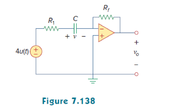
For the op amp circuit of Fig. 7.138, let R1 = 10 kΩ, Rf = 30 kΩ, C = 20 μF, and v(0) = 1 V. Find v0.
Find the output voltage
Answer to Problem 73P
The output voltage
Explanation of Solution
Given data:
Refer to Figure 7.138 in the textbook.
The value of capacitance
The source voltage
The value of resistance
The value of feedback resistance
The initial voltage v(0) or
Formula used:
Write the expression to find the time constant for an RC circuit.
Here,
C is the capacitance of the capacitor.
Write the general expression for the unit step function.
Calculation:
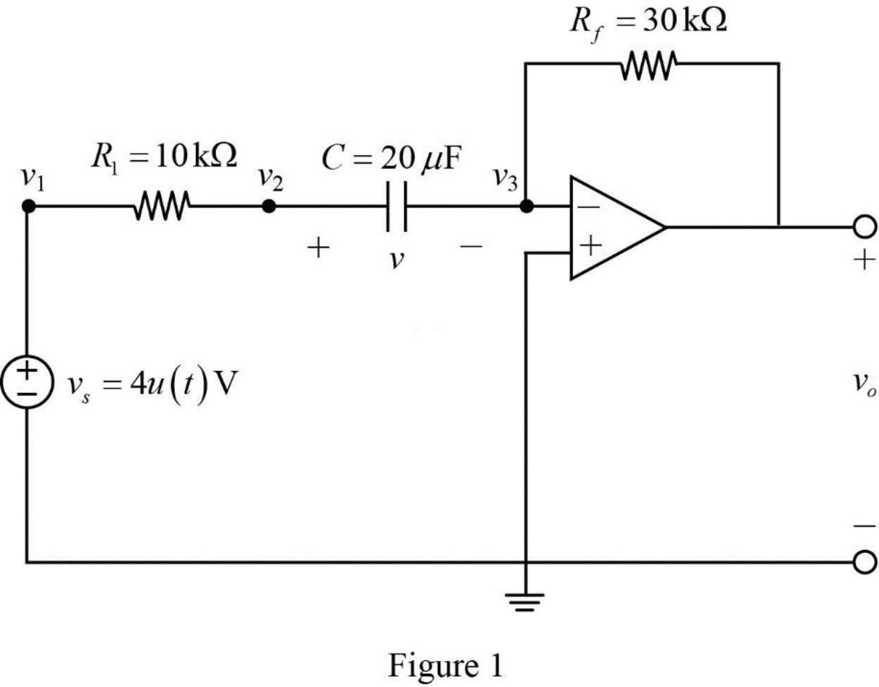
The given Figure 7.138 is redrawn as shown in Figure 1.
The given source voltage is,
Apply the unit step function in equation (2) to equation (3).
For
Since the source voltage
For
The source voltage is,
In Figure 1, apply Kirchhoff’s current law at node
In Figure 1, apply Kirchhoff’s current law at node
From Figure 1, the voltages are,
Substitute
Substitute
Rearrange the equation as follows,
The equation is similar to the equation (7.42) in the textbook.
Hence,
In Figure 1, the Thevenin resistance
Substitute
Substitute the units
Substitute 1 V for
On differentiating the above equation as follows,
Substitute
Substitute
Apply the unit step function in equation (2) to equation (9).
Conclusion:
Thus, the output voltage
Want to see more full solutions like this?
Chapter 7 Solutions
EBK FUNDAMENTALS OF ELECTRIC CIRCUITS


- I. An op amp has a GBP of 106. A 0.3 µV sinusoidal signal at 5 KHz is required to be amplified to 5 V. Calculate the gains and draw the schematic circuit to achieve this.arrow_forwardC R The OP-AMP with R = 10 kN and C = 0.4 µF has the input vs(t) = 10(1 – e-25t) V. Find vo(t) for t > 0. + + vs(t) vo(t)arrow_forwardIn the forced commutation circuit shown what is the minimum value of C in nF so that SCR does not get turned on due to re-applied dv/dt. The SCR has minimum charging current of 5 mA to turn it on and the junction capacitance is 30 pF. V₁ = 400 V R = 80 92 C Tarrow_forward
- 7:44 ( Teams PBL-1 Your Friend Saad was selected to attend the Electronics workshop on “Electronic Circuits" organized by the university. In the workshop, he was exposed to many topics such as voltage divider circuits, dependent voltage source, dependent current source, independent voltage source, independent current source, application of Thevenin and Norton theorem, maximum power transfer. There were some customers’ requirements same were discussed in the workshop. Apply the concepts of the above-mentioned topics, each participant must fulfill the customer requirements. I) The input available DC voltage is 220 V and customer wants to supply the output of 30V and 50V. The available ready stock is source voltage as mentioned above and resistors values can be chosen from 1-300 KQ. Apply the concept of voltage divider with values of resistance is in k2, one value of the resistor is the last digit of your NUTECH ID and other may vary (depend on your calculations). II) Now you have two…arrow_forwardIf the collector supply voltage is increased to 15 V in Fig. 7-30b, what is the collector-emitter voltage for VBB = 1.8 V?arrow_forwardAn op amp has a GBP of 10°. A 0.3 µV sinusoidal signal at 5 KHz is required to be amplified to 5 V. Calculate the gains.arrow_forward
- Subject : Power electronicsarrow_forwardSOLVE STEP BY STEP IN DIGITAL FORMAT A 12 volt battery is connected to a series circuit in which the inductor is 1/4 Henry and the resistance is 25 Ohm. Determine the current i, if the initial current is zero.arrow_forwardI need details solution else I will complaint against youarrow_forward
 Introductory Circuit Analysis (13th Edition)Electrical EngineeringISBN:9780133923605Author:Robert L. BoylestadPublisher:PEARSON
 Delmar's Standard Textbook Of ElectricityElectrical EngineeringISBN:9781337900348Author:Stephen L. HermanPublisher:Cengage Learning
 Programmable Logic ControllersElectrical EngineeringISBN:9780073373843Author:Frank D. PetruzellaPublisher:McGraw-Hill Education
 Fundamentals of Electric CircuitsElectrical EngineeringISBN:9780078028229Author:Charles K Alexander, Matthew SadikuPublisher:McGraw-Hill Education
 Electric Circuits. (11th Edition)Electrical EngineeringISBN:9780134746968Author:James W. Nilsson, Susan RiedelPublisher:PEARSON
 Engineering ElectromagneticsElectrical EngineeringISBN:9780078028151Author:Hayt, William H. (william Hart), Jr, BUCK, John A.Publisher:Mcgraw-hill Education,