
Concept explainers
Videos
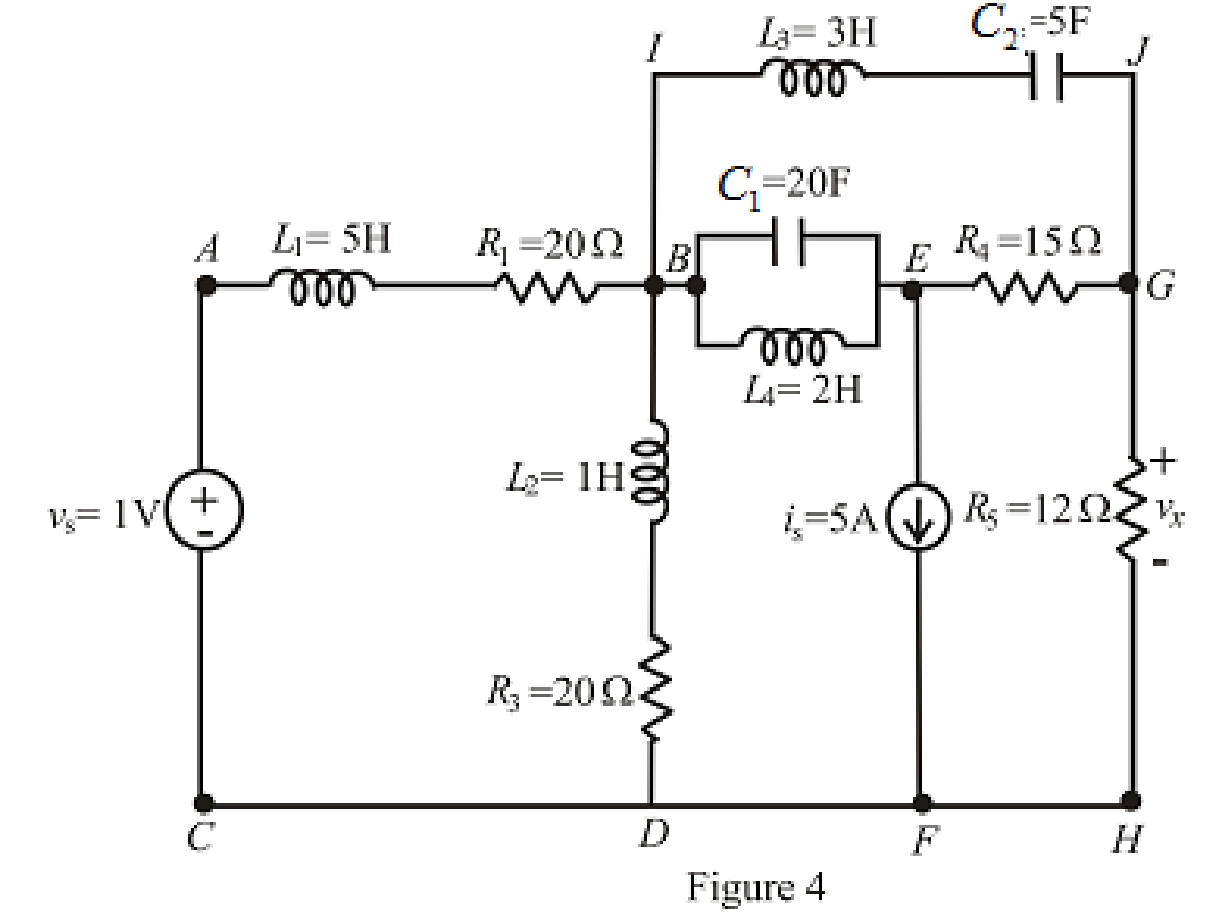
Calculate the voltage labeled vx in Fig. 7.52, assuming the circuit has been running a very long time, if (a) a 10 Ω resistor is connected between terminals x and y; (b) a 1 H inductor is connected between terminals x and y; (c) a 1 F capacitor is connected between terminals x and y; (d) a 4 H inductor in parallel with a 1 Ω resistor is connected between terminals x and y.
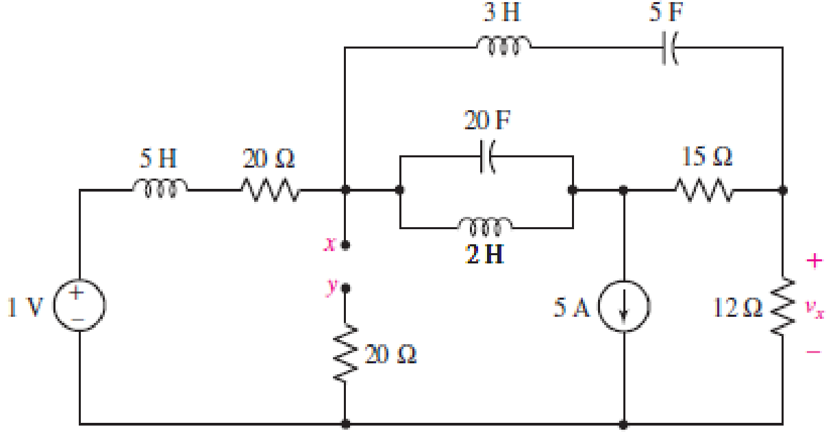
FIGURE 7.52
(a)
Find the voltage
Answer to Problem 29E
The voltage
Explanation of Solution
Given data:
Value of resistance connected between terminals
Calculation:
The redrawn circuit is shown in Figure 1 as follows:
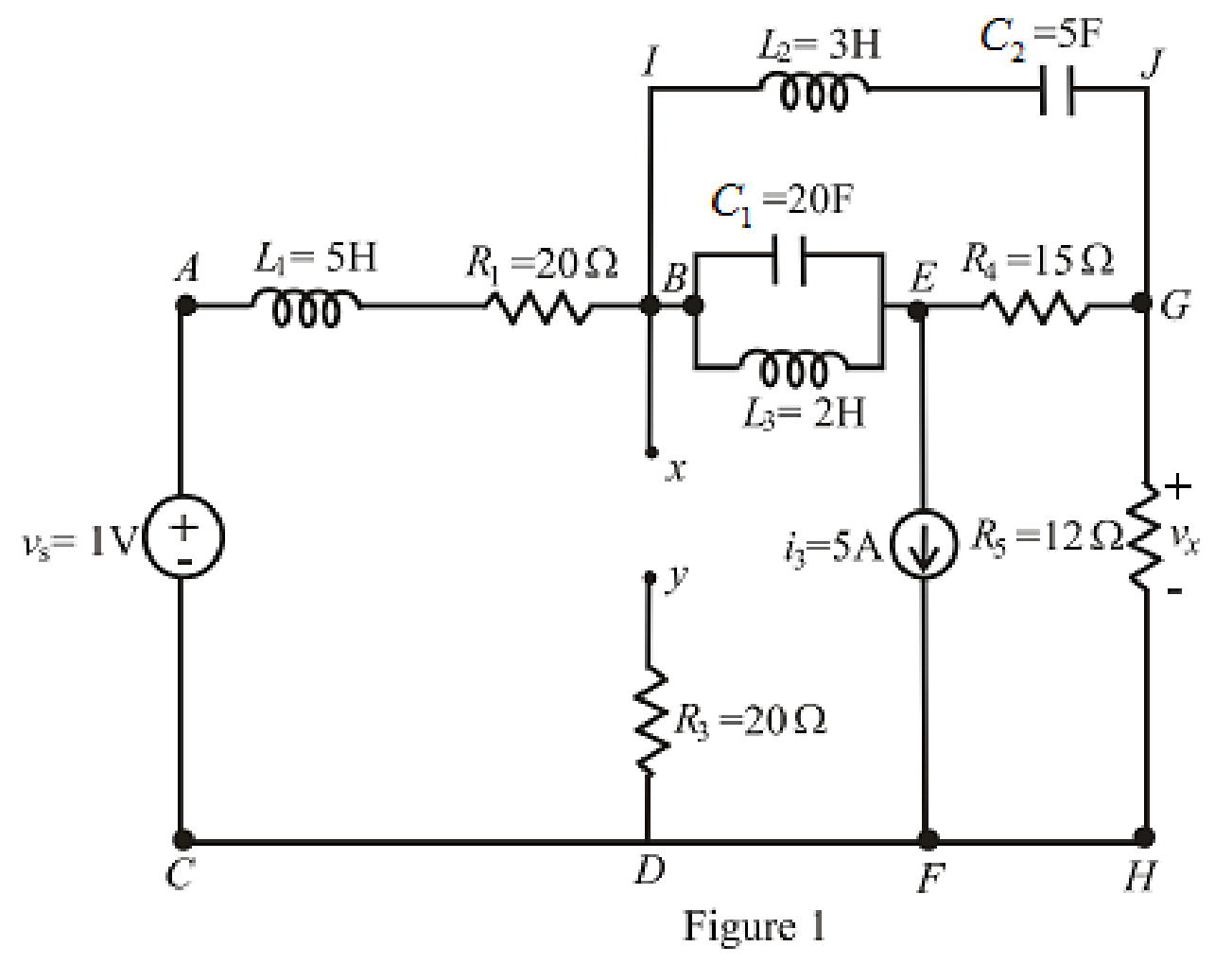
Here,
The redrawn circuit is shown in Figure 2.
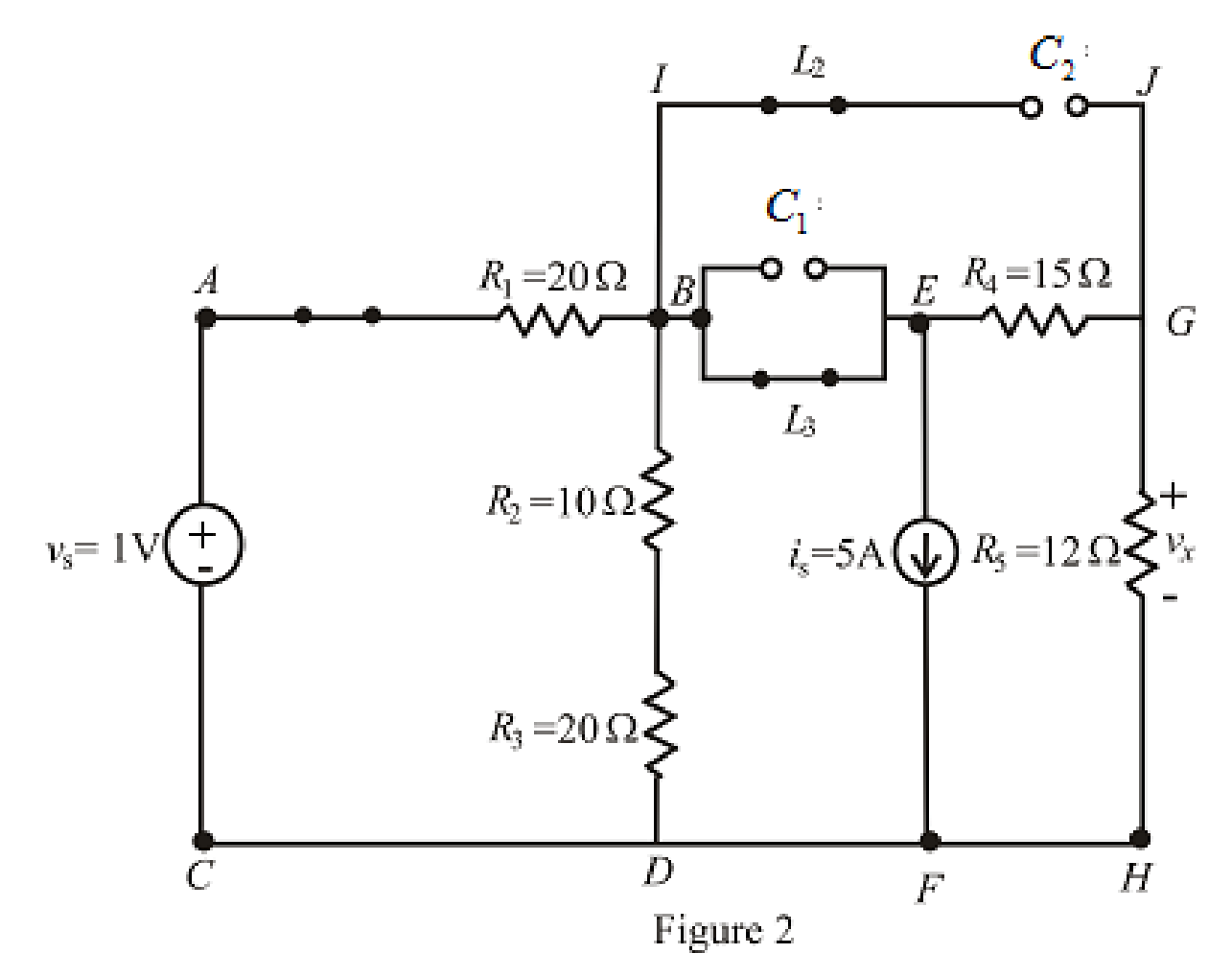
Refer to the Figure 2:
When steady state is reached, all the inductors connected are short circuited and all the capacitors connected are open circuited.
The equivalent resistance for series combination across branch is as follows:
Substitute
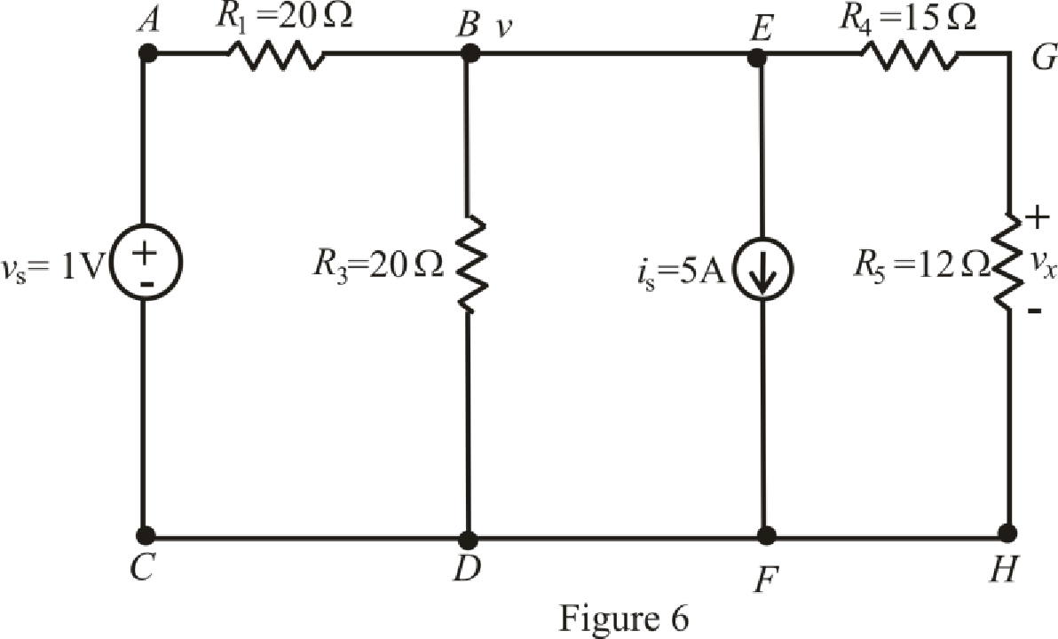
The redrawn circuit is shown in Figure 3 as follows:
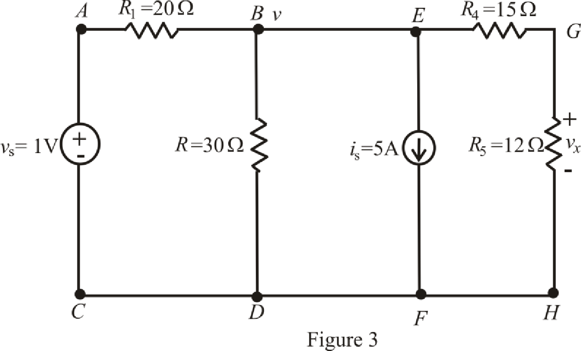
Refer to the redrawn Figure 3:
The expression for the nodal analysis at node voltage
Here,
The expression for the current across the resistance
The expression for the voltage across the resistance
The current across the resistances
Substitute
Solve for
Substitute
Substitute
Conclusion:
Thus, the voltage
(b)
Find the voltage
Answer to Problem 29E
The voltage
Explanation of Solution
Given Data:
Value of inductor connected between terminals
Calculation:
The redrawn circuit with inductor connected across branch
The redrawn circuit is shown in Figure 4 as follows:
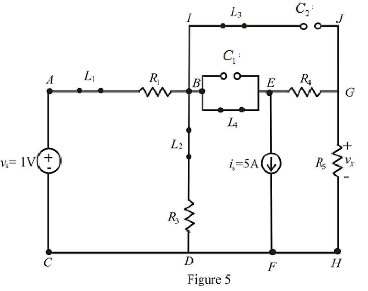
Refer to the Figure 5:
When steady state is reached, the inductor connected across branch
The redrawn circuit is shown in Figure 6 as follows:
The expression for the nodal analysis at node voltage
The expression for the current across the resistance
The expression for the current across the resistance
The current across the resistances
Substitute
Solve for
Substitute
Substitute
Conclusion:
Thus, the voltage
(c)
Find the voltage
Answer to Problem 29E
The voltage
Explanation of Solution
Given data:
Value of capacitor connected between terminals
Calculation:
The redrawn circuit of capacitor connected across branch
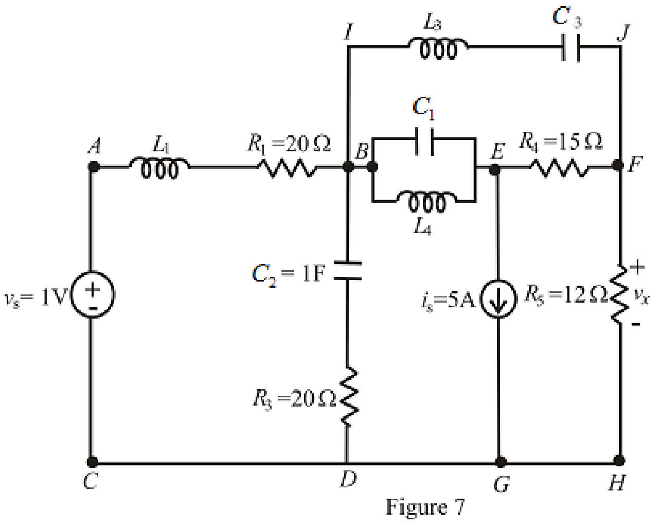
Refer to the redrawn Figure 7:
The redrawn circuit is shown in Figure 8 as follows:
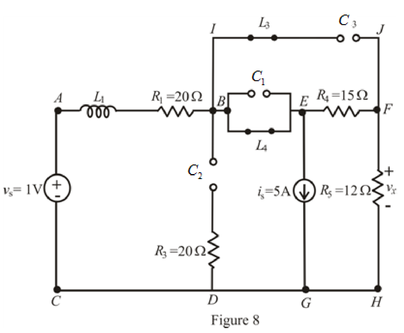
When steady state is reached, thecapacitors connected across branch
The redrawn circuit is shown in Figure 9 as follows:
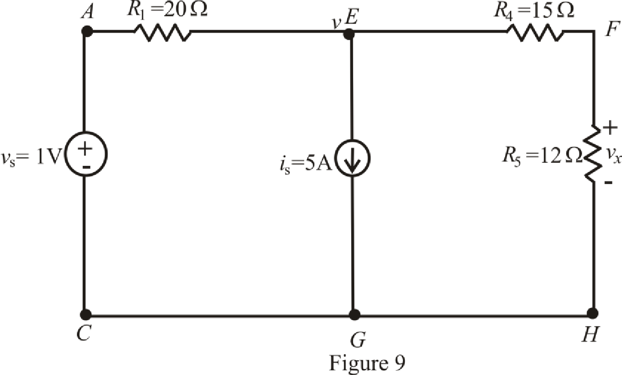
Refer to the Figure 9:
The expression for the nodal analysis at node voltage
The expression for the current across the resistance
The expression for the voltage across the resistance
The current across the resistances
Substitute
Solve for
Substitute
Substitute
Conclusion:
Thus, the voltage
(d)
Find the voltage
Answer to Problem 29E
The voltage
Explanation of Solution
Given Data:
Value of inductor connected between terminal
Value of resistor connected in parallel with inductor across terminal
Calculation:
The redrawn circuit is shown in Figure 10:
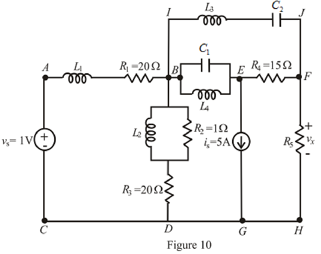
Refer to the redrawn Figure 10:
The redrawn circuit is shown in Figure 11 as follows:
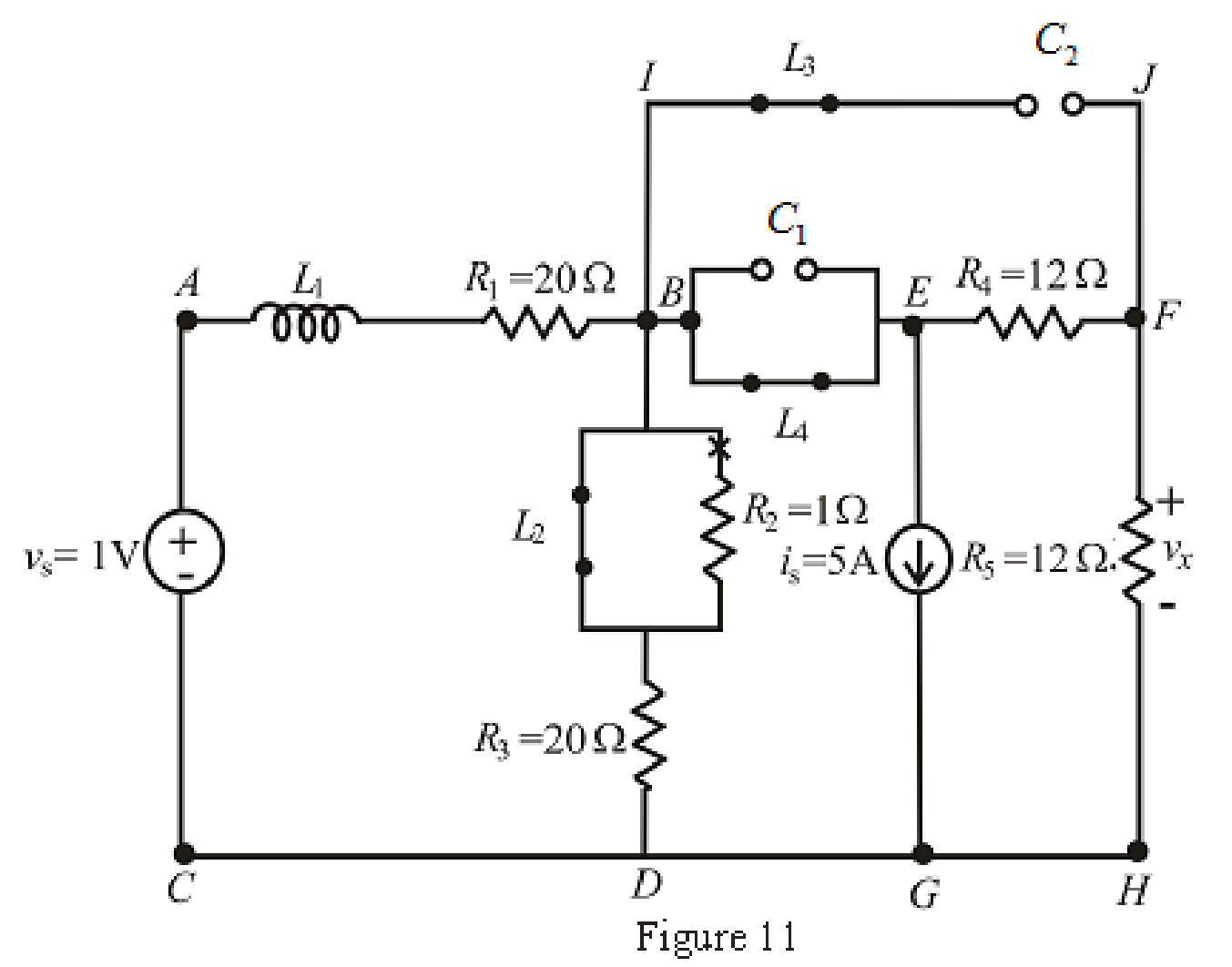
When steady state is reached, the inductor connected across branch
The redrawn circuit is shown in Figure 12,
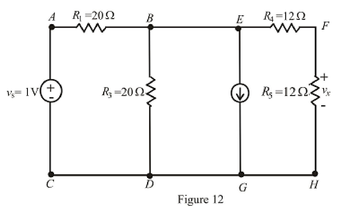
Refer to the Figure 12:
The expression for the nodal analysis at node voltage
The expression for the current across the resistance
The expression for the voltage across the resistance
The current across the resistances
Substitute
Solve for
Substitute
Substitute
Conclusion:
Thus, the voltage
Want to see more full solutions like this?
Chapter 7 Solutions
ENGINEERING CIRCUIT...(LL)>CUSTOM PKG.<


- For the circuit shown below (assume a switch is closed for enough time such that the inductor is fully charge) find the voltage labeled v at = 200 ms, after the switch is openarrow_forwardTwo capacitors are in series with a voltage source of 15 V. If the capacitors are rated at 10 μF and 5 μF respectively, calculate: Equivalent capacitance Equivalent charge, Q1 , and Q2 V1 and V2arrow_forwardA 100µF capacitor is connected in series with a 150volt voltmeter that has a resistance of 1,000 ohms per volt. Calculate the reading of the voltmeter at the instant when t equals the time constant following the closing if the switch that impresses 120volts on the circuit.arrow_forward
- 19arrow_forwardTwo capacitors are in parallel with a voltage source of 15 V. If the capacitors are rated at 10 μF and 5 μF respectively, calculate: Equivalent capacitance V1 and V2 Equivalent charge, Q1 , and Q2arrow_forwardUNDER DC CONDITIONS .NEED ONLY NEAT HANDWRITTEN SOLUTION ,OTHERWISE DISLIKE .arrow_forward
- Find ID and VDSarrow_forwardCalculate v₁ and it for each of the circuits depicted in Fig. 7.48, if is = 1 mA and vs 2.1 V. = Vs is + 4.7 ΚΩ M (a) 4.7 ΚΩ. (c) 12 nH iL 12 nH VL is Vs + 4.7 ΚΩ 14 ΚΩ M (b) 4.7 ΚΩ (d) iL 12 nH iL m +51 12 nH 14 ΚΩ ww VL ell +51 VLarrow_forwardTwo capacitors having voltage 2F and 4F are connected in series. This combination is connected to a 100V supply, calculate the voltage across the 2F capacitor. a) 66.67V b) 33.33V c) 100V d) 0Varrow_forward
- Nonearrow_forwardFind the time constant, initial and final inductor current. 10 V Time constant: 0.07 s A) Initial current: 5 A Final current: 2 A Time constant: 0.07 s B) Initial current: 4 A Final current: 6 A Time constant: 0.05 s Initial current: 4 A Final current: 5 A Time constant: 0.05 s D) Initial current: 5 A Final current: 6 A +1 2 Ω www t = 0 3 Ω ww i Harrow_forwardA circuit consists of a 5μF capacitor connected in series with a 10 kΩ resistor with a switchable 80V DC supply. When the supply is connected, calculate:a. the time constantb. the maximum currentc. the voltage across the capacitor after 0.5 sd. the current flowing after one time constante. the voltage across the resistor after 0.1sf. the time for the capacitor voltage to reach 45Vg. the initial rate of voltage risearrow_forward
 Introductory Circuit Analysis (13th Edition)Electrical EngineeringISBN:9780133923605Author:Robert L. BoylestadPublisher:PEARSON
 Delmar's Standard Textbook Of ElectricityElectrical EngineeringISBN:9781337900348Author:Stephen L. HermanPublisher:Cengage Learning
 Programmable Logic ControllersElectrical EngineeringISBN:9780073373843Author:Frank D. PetruzellaPublisher:McGraw-Hill Education
 Fundamentals of Electric CircuitsElectrical EngineeringISBN:9780078028229Author:Charles K Alexander, Matthew SadikuPublisher:McGraw-Hill Education
 Electric Circuits. (11th Edition)Electrical EngineeringISBN:9780134746968Author:James W. Nilsson, Susan RiedelPublisher:PEARSON
 Engineering ElectromagneticsElectrical EngineeringISBN:9780078028151Author:Hayt, William H. (william Hart), Jr, BUCK, John A.Publisher:Mcgraw-hill Education,