
Concept explainers
Videos
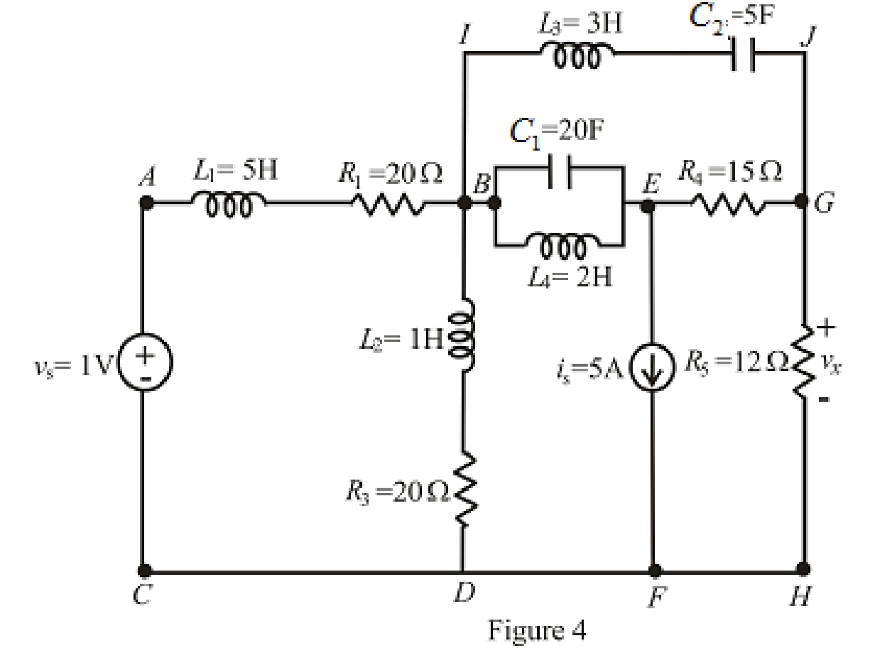
Calculate the voltage labeled vx in Fig. 7.52, assuming the circuit has been running a very long time, if (a) a 10 Ω resistor is connected between terminals x and y; (b) a 1 H inductor is connected between terminals x and y; (c) a 1 F capacitor is connected between terminals x and y; (d) a 4 H inductor in parallel with a 1 Ω resistor is connected between terminals x and y.
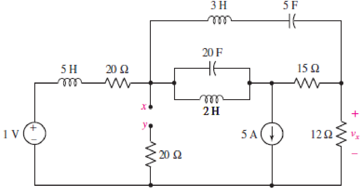
FIGURE 7.52
(a)
Find the voltage
Answer to Problem 29E
The voltage
Explanation of Solution
Given data:
Value of resistance connected between terminals
Calculation:
The redrawn circuit is shown in Figure 1 as follows:
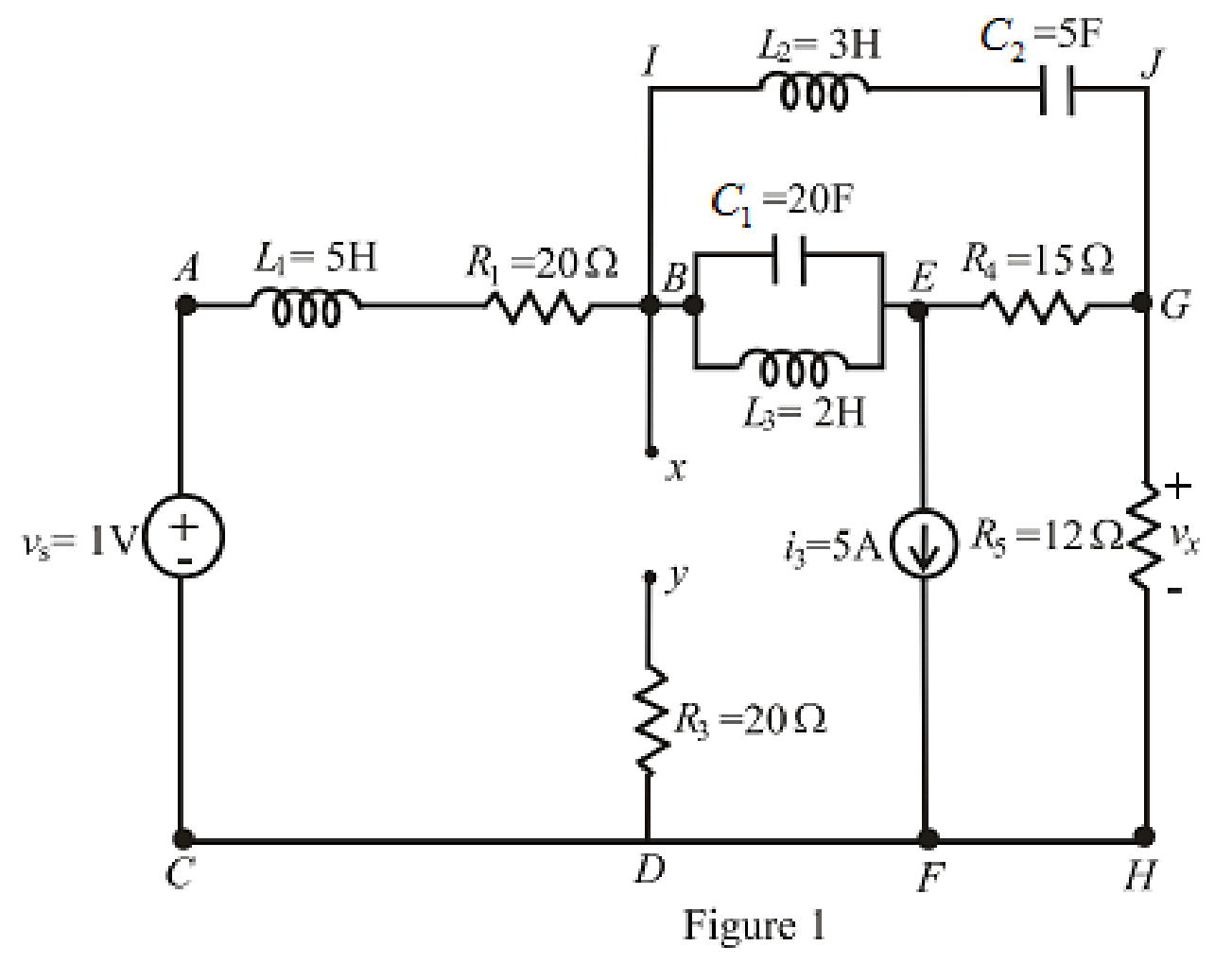
Here,
The redrawn circuit is shown in Figure 2.
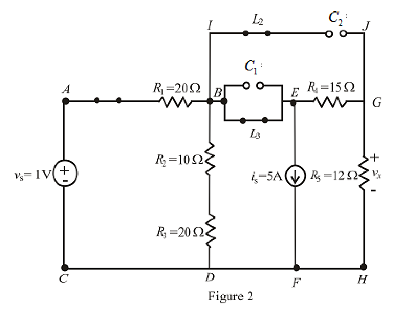
Refer to the Figure 2:
When steady state is reached, all the inductors connected are short circuited and all the capacitors connected are open circuited.
The equivalent resistance for series combination across branch is as follows:
Substitute
The redrawn circuit is shown in Figure 3 as follows:
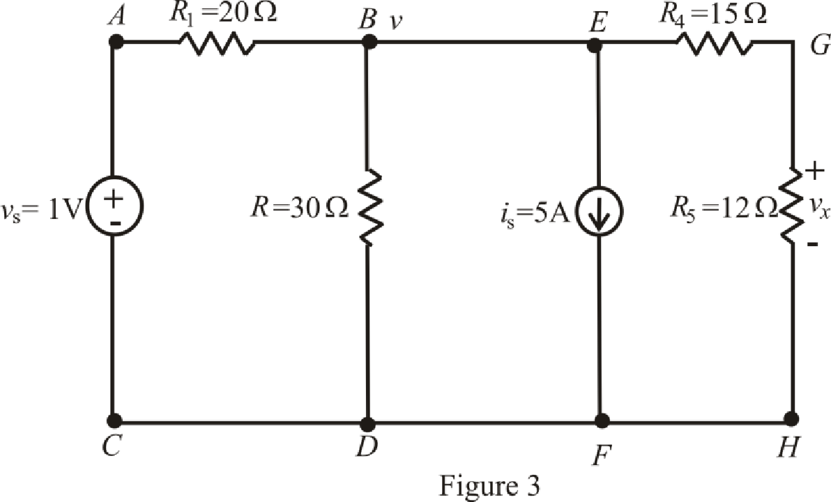
Refer to the redrawn Figure 3:
The expression for the nodal analysis at node voltage
Here,
The expression for the current across the resistance
The expression for the voltage across the resistance
The current across the resistances
Substitute
Solve for
Substitute
Substitute
Conclusion:
Thus, the voltage
(b)
Find the voltage
Answer to Problem 29E
The voltage
Explanation of Solution
Given Data:
Value of inductor connected between terminals
Calculation:
The redrawn circuit with inductor connected across branch
The redrawn circuit is shown in Figure 4 as follows:
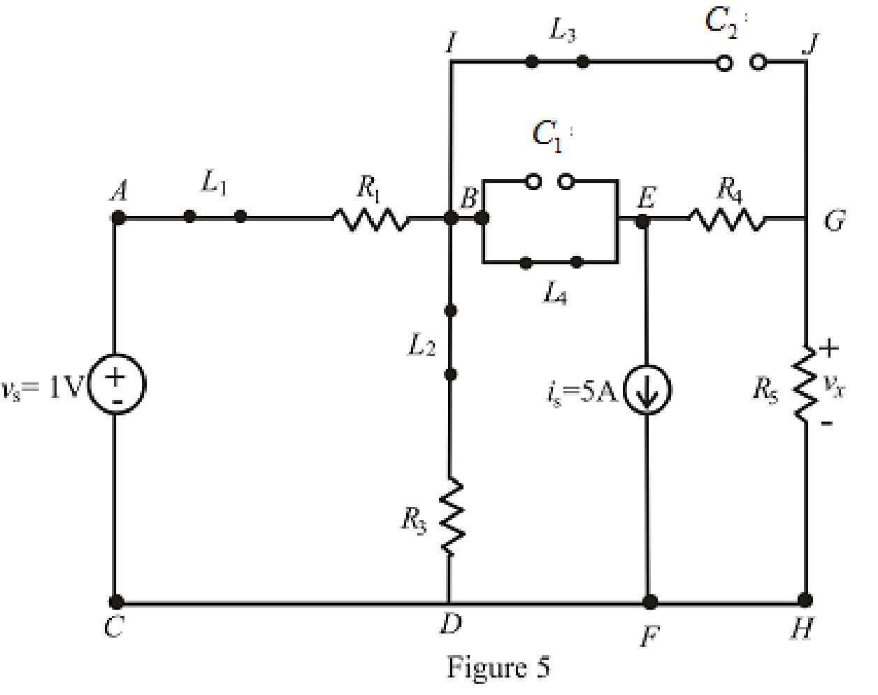
Refer to the Figure 5:
When steady state is reached, the inductor connected across branch
The redrawn circuit is shown in Figure 6 as follows:
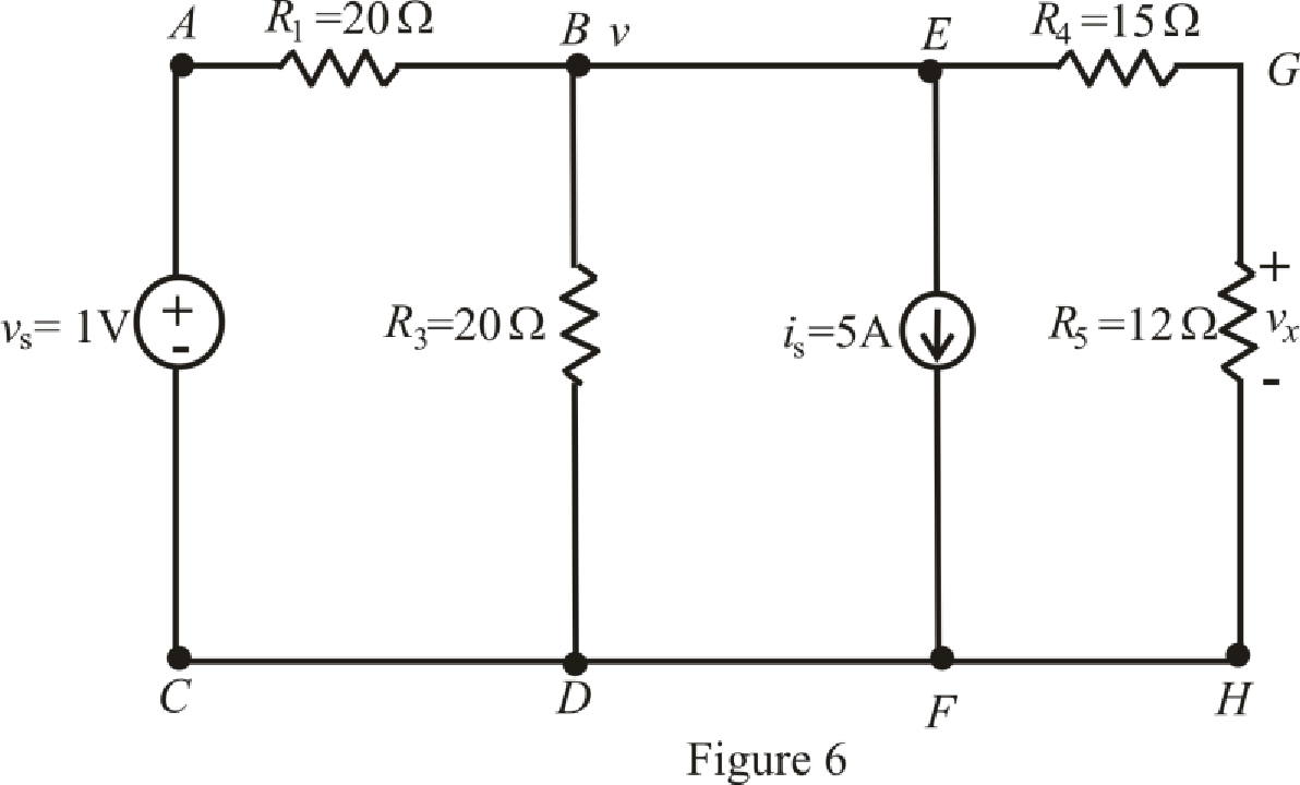
The expression for the nodal analysis at node voltage
The expression for the current across the resistance
The expression for the current across the resistance
The current across the resistances
Substitute
Solve for
Substitute
Substitute
Conclusion:
Thus, the voltage
(c)
Find the voltage
Answer to Problem 29E
The voltage
Explanation of Solution
Given data:
Value of capacitor connected between terminals
Calculation:
The redrawn circuit of capacitor connected across branch
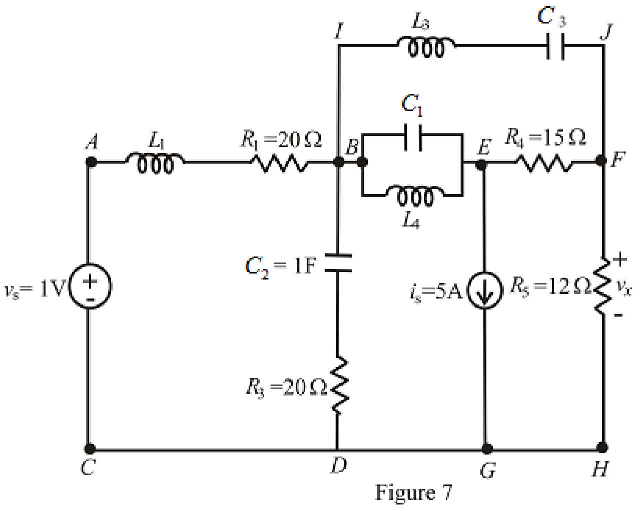
Refer to the redrawn Figure 7:
The redrawn circuit is shown in Figure 8 as follows:
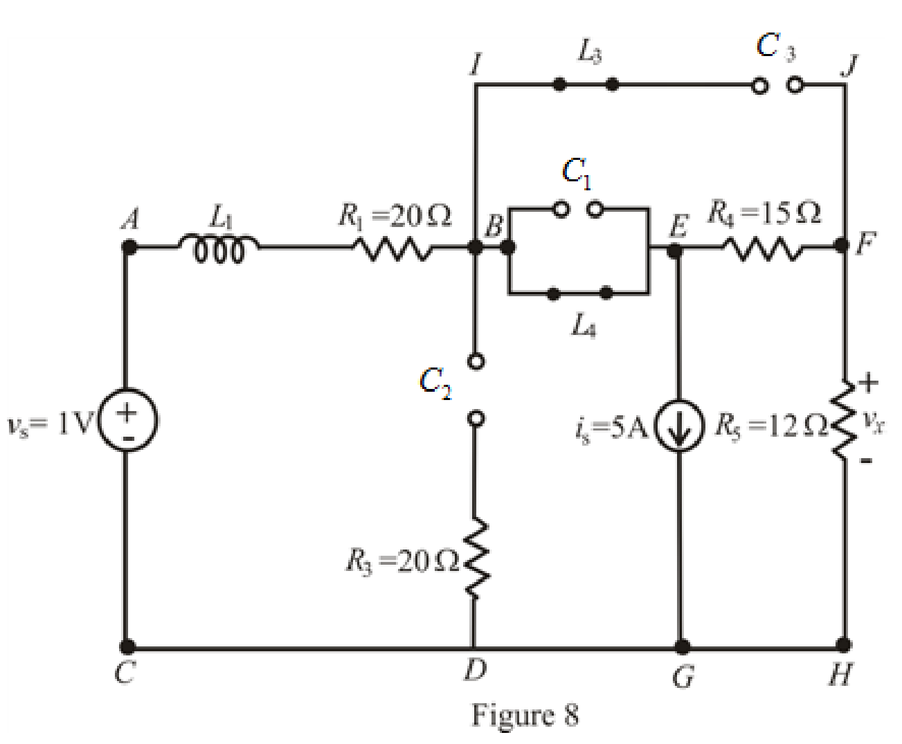
When steady state is reached, thecapacitors connected across branch
The redrawn circuit is shown in Figure 9 as follows:
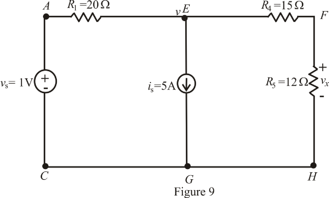
Refer to the Figure 9:
The expression for the nodal analysis at node voltage
The expression for the current across the resistance
The expression for the voltage across the resistance
The current across the resistances
Substitute
Solve for
Substitute
Substitute
Conclusion:
Thus, the voltage
(d)
Find the voltage
Answer to Problem 29E
The voltage
Explanation of Solution
Given Data:
Value of inductor connected between terminal
Value of resistor connected in parallel with inductor across terminal
Calculation:
The redrawn circuit is shown in Figure 10:
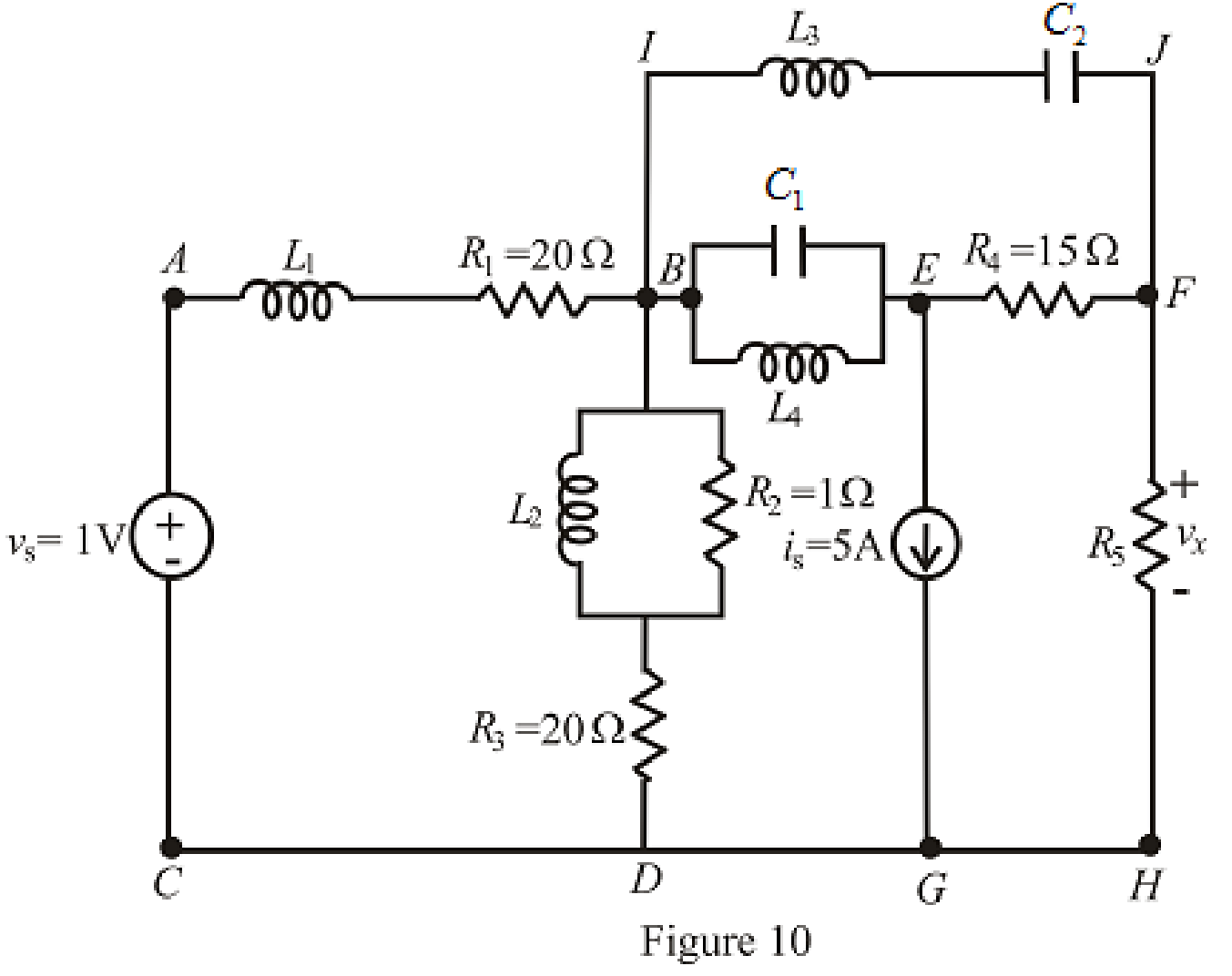
Refer to the redrawn Figure 10:
The redrawn circuit is shown in Figure 11 as follows:
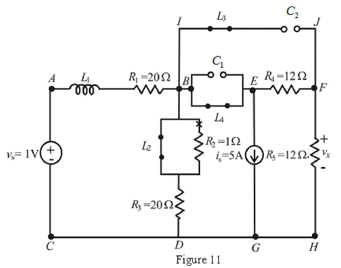
When steady state is reached, the inductor connected across branch
The redrawn circuit is shown in Figure 12,
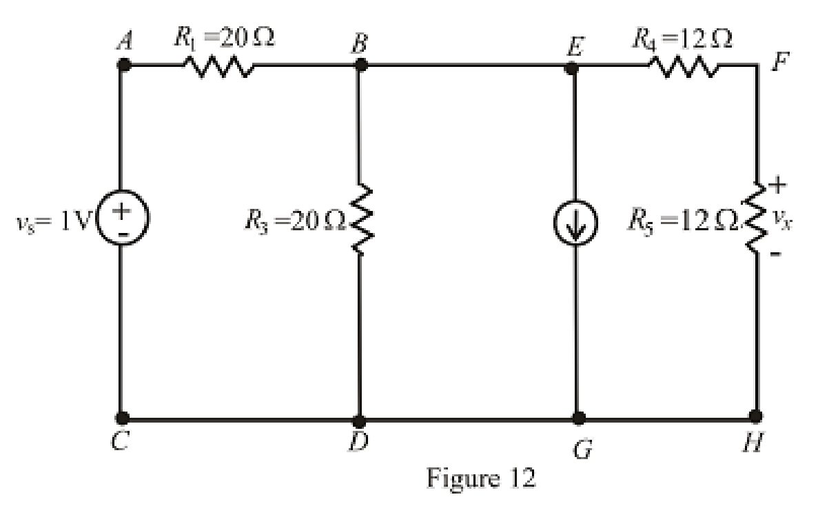
Refer to the Figure 12:
The expression for the nodal analysis at node voltage
The expression for the current across the resistance
The expression for the voltage across the resistance
The current across the resistances
Substitute
Solve for
Substitute
Substitute
Conclusion:
Thus, the voltage
Want to see more full solutions like this?
Chapter 7 Solutions
ENGINEERING CIRCUIT ANALYSIS ACCESS >I<


- In response to a change introduced by a switch at t = 0, the current flowing through a 100 μF capacitor, defined in accordance with the passive sign convention, was observed to be i(t) = −0.4e−0.5t mA (for t > 0). If the final energy stored in the capacitor (at t = ∞) is 0.2 mJ, determine υ(t) for t ≥ 0.arrow_forwardA 30 μF capacitor is connected in parallel with a coil of inductance 50 mH andunknown resistance R across a 120 V, 50 Hz supply. If the circuit has an overallpower factor of unity, find (a) the value of R, (b) the current in the coil, and (c)the supply current.arrow_forwardThe switch in the circuit seen in fig 7.54arrow_forward
- A 100µF capacitor is connected in series with a 150volt voltmeter that has a resistance of 1,000 ohms per volt. Calculate the reading of the voltmeter at the instant when t equals the time constant following the closing if the switch that impresses 120volts on the circuit.arrow_forward* Determine the charge stored on a 2.2 µF capacitor if the capacitor’s voltage is 5 V. *In some integrated circuits, the insulator or dielectric is silicon dioxide, which has a relative permittivity of 4. If a square capacitor measuring 10 µm on edge, has a capacitance of 100 fF, what is the separation distance between the capacitor’s plates, in µm?arrow_forwardThe voltage pulse applied to the 100 mH inductor shown is 0 for t<0 and is given by the expression v(t)=20te−10t V for t>0. Also assume i=0 for t≤0. Sketch the current as a function of time.arrow_forward
- 6 A capacitor is constructed with parallel metal plates, If the plate separation is 2 mm and the capacitance is given to 1 nano Farads, determine the area of the parallel plates of the device. Select one: a. 0.12 square meters b. 0.23 square meters c. 0.27 square meters d. 0.20 square metersarrow_forwardGiven fig. 7. Find vc(0) 8. Find vc(t) 9. Find vc(∞)arrow_forwardFind Leq between the terminals a,b for the circuits shown below. Assuming the initial energy stored in the inductors is zero.arrow_forward
- 1. Theoretically calculate the voltage across the capacitor in the circuit of Figure 1 when t = 0 s, 5 s, 10 s, 20 s, 30 s, 40 s, and 60 s, assuming that the circuit is under DC conditions when t < 0 s and the switch is opened at t = 0 s. 2. Compare the calculated voltage at t = 20 s with the experimentally measured ∆?.arrow_forwardThe terminal voltage of a 2-H inductor is v = 10(1 – t ) V. Find the current flowing through it at t = 4s and the energy stored in it at t = 4 s. Assume i(0) = 2 A.arrow_forwardAn iron ring 20 cm mean radius is made of square of iron of 3 cm × 3 cm cross-section and is uniformly wound with 350 turns of wire of 2 mm2 cross-section. Calculate the value of the self-inductance of the coil. Assume μr = 800.arrow_forward
 Introductory Circuit Analysis (13th Edition)Electrical EngineeringISBN:9780133923605Author:Robert L. BoylestadPublisher:PEARSON
 Delmar's Standard Textbook Of ElectricityElectrical EngineeringISBN:9781337900348Author:Stephen L. HermanPublisher:Cengage Learning
 Programmable Logic ControllersElectrical EngineeringISBN:9780073373843Author:Frank D. PetruzellaPublisher:McGraw-Hill Education
 Fundamentals of Electric CircuitsElectrical EngineeringISBN:9780078028229Author:Charles K Alexander, Matthew SadikuPublisher:McGraw-Hill Education
 Electric Circuits. (11th Edition)Electrical EngineeringISBN:9780134746968Author:James W. Nilsson, Susan RiedelPublisher:PEARSON
 Engineering ElectromagneticsElectrical EngineeringISBN:9780078028151Author:Hayt, William H. (william Hart), Jr, BUCK, John A.Publisher:Mcgraw-hill Education,