
Concept explainers
Videos
(a)
Find the energy stored in the element at time
(a)
Answer to Problem 68E
The energy stored in the element at time
Explanation of Solution
Given data:
Write a general expression to calculate the energy stored in an inductor.
Here,
Given data:
Refer to Figure 7.82 in the textbook.
The value of initial current through inductor
Calculation:
Substitute
Substitute
Simplify the above equation to find
Conclusion:
Thus, the energy stored in the element at time
(b)
Determine the value of
(b)
Answer to Problem 68E
The value of
Explanation of Solution
Calculation:
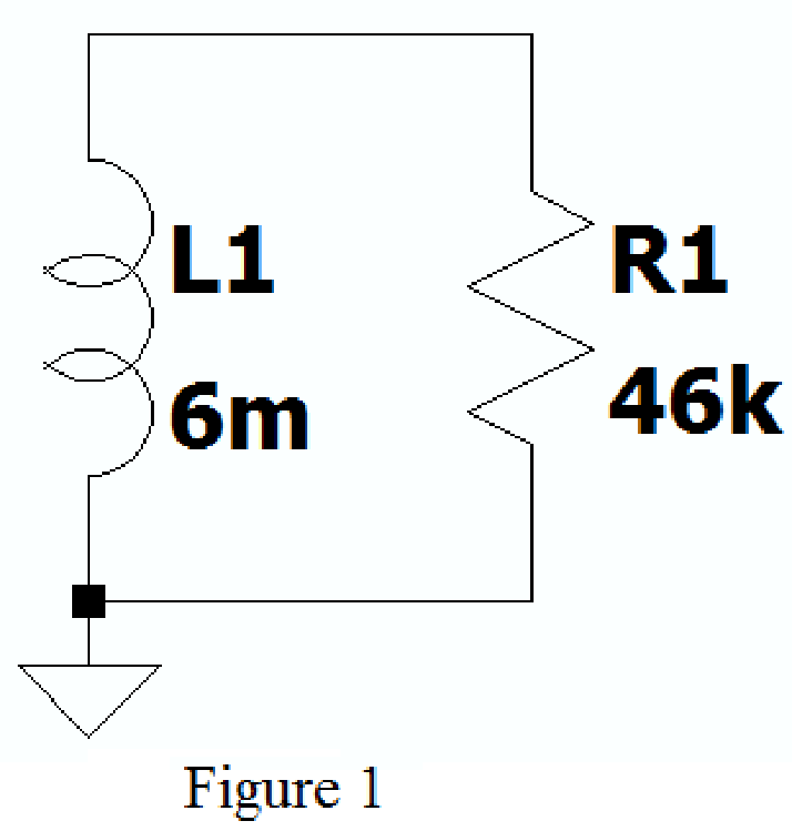
Create the new schematic in LTspice with series connected resistor and inductor of given circuit as shown in Figure 1.
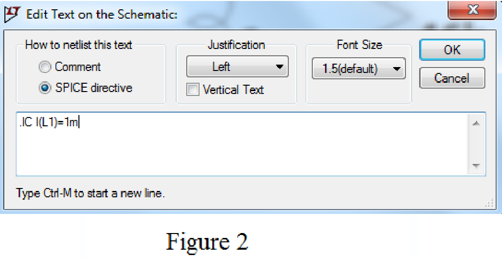
Using SPICE Directive mention the command .ic I(L1)=1m as shown in Figure 2.
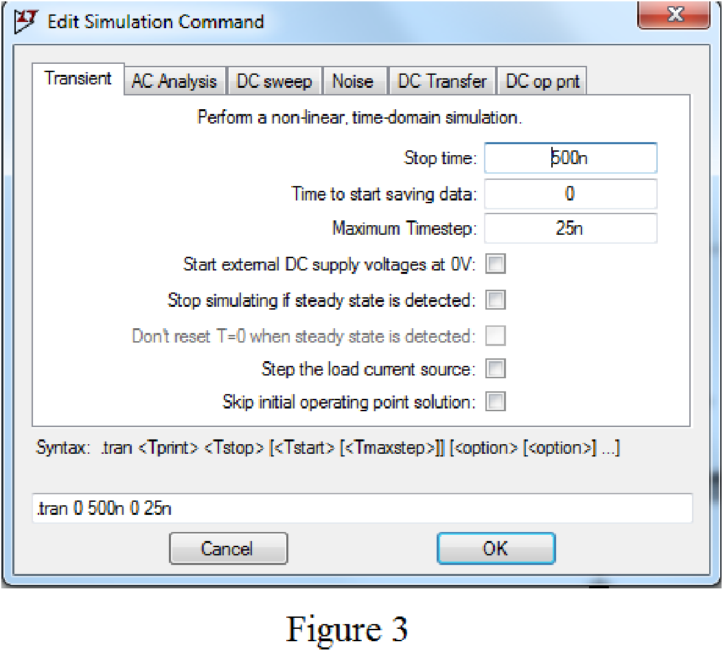
Enter the stop time as 500ns, time to start saving data as 0, and maximum Timestep as 25ns in Edit simulation Cmd as shown in Figure 3.
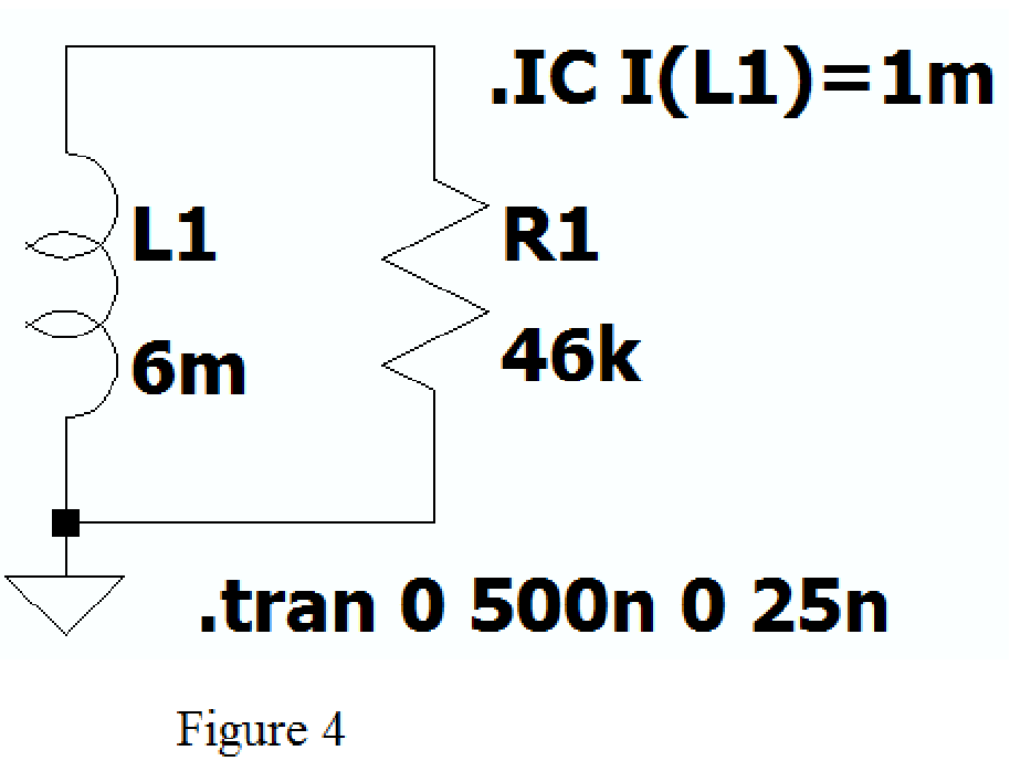
After adding the Spice directives the circuit shows as in Figure 4.
Now run the simulation and place the probe at inductor, the plot of the current through inductor with respect to time is shown as shown in Figure 5.
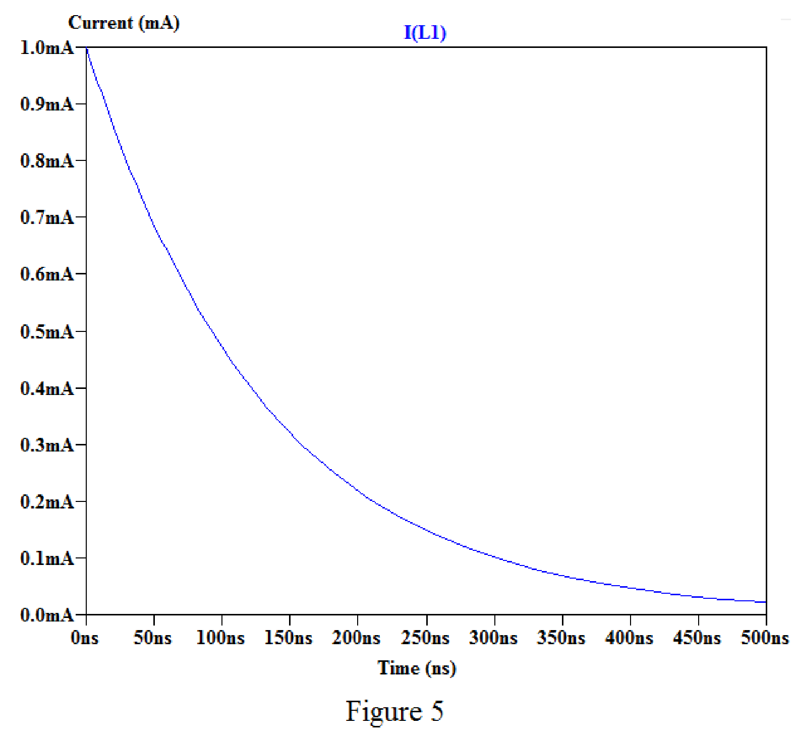
By placing the cursor on the graph, we obtain the current values for different time as shown in below.
For time
For time
For time
For time
Conclusion:
Thus, the value of
(c)
Find the value of initial energy remains in the inductor at time
(c)
Answer to Problem 68E
The value of initial energy remains in the inductor at time
Explanation of Solution
Calculation:
Refer to part (b), the value of current at time
Substitute
Substitute
Simplify the above equation to find
Substitute
Substitute
Simplify the above equation to find
Conclusion:
Thus, the value of initial energy remains in the inductor at time
Want to see more full solutions like this?
Chapter 7 Solutions
ENGINEERING CIRCUIT ANALYSIS ACCESS >I<


- The voltage pulse applied to the 100 mH inductor shown is 0 for t<0 and is given by the expression v(t)=20te−10t V for t>0. Also assume i=0 for t≤0. Sketch the current as a function of time.arrow_forwardTwo capacitors, of capacitance 3µF and 5µF, are connected as shown to batteries A and B which have EMF 4 V and 12 V respectively. What is the energy stored in each of the capacitors? Calculate also the stored energy in each capacitor when the terminals of battery A are reversed, and when the battery B is disconnected, and the points X and Y are connected together.arrow_forwardA 100µF capacitor is connected in series with a 150volt voltmeter that has a resistance of 1,000 ohms per volt. Calculate the reading of the voltmeter at the instant when t equals the time constant following the closing if the switch that impresses 120volts on the circuit.arrow_forward
- * Determine the charge stored on a 2.2 µF capacitor if the capacitor’s voltage is 5 V. *In some integrated circuits, the insulator or dielectric is silicon dioxide, which has a relative permittivity of 4. If a square capacitor measuring 10 µm on edge, has a capacitance of 100 fF, what is the separation distance between the capacitor’s plates, in µm?arrow_forward7. 7.27 In the circuit the voltage and current expressions are v=48e−25t V, t≥0;i=12e−25t mA, t≥0+.Find1. a) R.2. b) C.3. c) τ (in milliseconds).4. d) the initial energy stored in the capacitor.5. e) the amount of energy that has been dissipated by the resistor 60ms after the voltage begins to decay.arrow_forward3. A ceramic capacitor has an effective plate area of 5cm2 separated by 0.1mm of ceramic of relative permittivity of 100. Calculate the capacitance in microfarads. If the capacitor is given a charge of 1.5 µC what will be the potential difference (pd) between plates? & calculate the energy stored in itarrow_forward
- A 20μF capacitor is subjected to a voltage pulse having a duration of 1 s. The pulse is described by the following equations: vc(t)={30t2 V,0≤t≤0.5 s;30(t−1)2 V,0.5 s≤t≤1 s;0elsewhere. Sketch the current pulse that exists in the capacitor during the 1 s interval.arrow_forwardThe current in a 20 mH inductor is known to be i=40 mA,t≤0; i=A1e−10,000t+A2e−40.000tA,t≥0. The voltage across the inductor (passive sign convention) is 28 V at t=0. 1. Find the expression for the voltage across the inductor for t>0. 2. Find the time, greater than zero, when the power at the terminals of the inductor is zero.arrow_forwardFor the circuit shown, calculate 1. the initial energy stored in the capacitors; 2. the final energy stored in the capacitors; 3. the total energy delivered to the black box; 4. the percentage of the initial energy stored that is delivered to the black box; and 5. the time, in milliseconds, it takes to deliver 7.5 mJ to the black box.arrow_forward
- The voltage across a 2µF capacitor is shown in Fig. Determine the waveformfor the capacitor current (a) Find mathematical expression of v(t) for 0 ≤ t ≤ 2 (b) Find mathematical expression of v(t) for 2 ≤ t ≤ 6arrow_forward6 A capacitor is constructed with parallel metal plates, If the plate separation is 2 mm and the capacitance is given to 1 nano Farads, determine the area of the parallel plates of the device. Select one: a. 0.12 square meters b. 0.23 square meters c. 0.27 square meters d. 0.20 square metersarrow_forward1. Calculate the capacitance between two parallel plates, each of which is 100 sq. Inches and 2 mm apart in air. 2. A capacitor is charged with 0.23 J of energy at a voltage of 48V. What is its capacitance? 3. A 50-uF capacitor is initially charged. Determine the initial charge of the 50-uF capacitor if the charge transferred to a 100-uF capacitor, when connected in parallel, is 200-uC.arrow_forward
 Introductory Circuit Analysis (13th Edition)Electrical EngineeringISBN:9780133923605Author:Robert L. BoylestadPublisher:PEARSON
 Delmar's Standard Textbook Of ElectricityElectrical EngineeringISBN:9781337900348Author:Stephen L. HermanPublisher:Cengage Learning
 Programmable Logic ControllersElectrical EngineeringISBN:9780073373843Author:Frank D. PetruzellaPublisher:McGraw-Hill Education
 Fundamentals of Electric CircuitsElectrical EngineeringISBN:9780078028229Author:Charles K Alexander, Matthew SadikuPublisher:McGraw-Hill Education
 Electric Circuits. (11th Edition)Electrical EngineeringISBN:9780134746968Author:James W. Nilsson, Susan RiedelPublisher:PEARSON
 Engineering ElectromagneticsElectrical EngineeringISBN:9780078028151Author:Hayt, William H. (william Hart), Jr, BUCK, John A.Publisher:Mcgraw-hill Education,