
Concept explainers
Videos
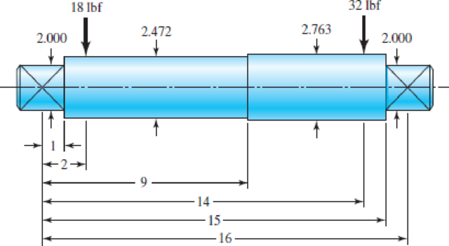
The steel shaft shown in the figure carries a 18-lbf gear on the left and a 32-lbf gear on the right. Estimate the first critical speed due to the loads, the shaft’s critical speed without the loads, and the critical speed of the combination.
Problem 7–32
Dimensions in inches.
The first critical speed of the shaft due to loads.
The critical speed of the shaft without loads.
The critical speed of the combination.
Answer to Problem 32P
The first critical speed of the shaft due to loads is
The critical speed of the shaft without loads is
The critical speed of the combination is
Explanation of Solution
Write the expression for the moment of the inertia.
Here, the diameter of the shaft is
Write the expression for the ratio of the bending moment to inertia.
Here, the bending moment across the shaft is
Write the expression for the ratio of the bending moment to inertia in terms of the spread sheet cell locations.
Substitute
Here, the young’s modulus of the shaft material is
Integrate the Equation (IV) with respect to x.
Substitute
Apply the boundary conditions.
Substitute
Substitute
Substitute
Substitute
Write the expression for the deflection at
Write the expression for the deflection at
Write the expression for the deflection of the shaft due to
Write the expression for the deflection of the shaft due to
Write the expression for the critical velocity due to load.
Here, the acceleration due to gravity is
Write the expression for the weight of the left gear.
Here, the physical constant of the material is
Write the expression for the weight of the right gear.
Write the expression for the critical velocity without load.
Here, the acceleration due to gravity is
Write the expression for the critical speed for the combination using Dunkerley’s equation.
Conclusion:
Draw the diagram for the shaft.
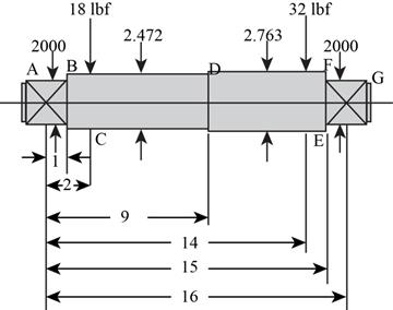
Figure-(1)
The Figure-(1) shows all the dimensions of the shaft.
Calculate the moment of inertia for the part
Substitute
Calculate the moment of inertia for the part
Substitute
Calculate the moment of inertia for the part
Substitute
Since the diameter of the shaft part
Substitute
Substitute
Substitute
Substitute
Substitute
Substitute
Here, the gravitational constant is
Substitute
Thus, he first critical speed of shaft due to loads is
Refer to table A-5 “Physical constants of the materials.” to obtain the weight density of the steel as
Substitute
Substitute
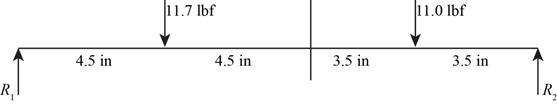
Draw the free body diagram for the calculated weights.
Substitute
Substitute
Substitute
Substitute
Substitute
Substitute
Substitute
Thus, the critical speed of shaft without loads is
Substitute
Thus, the critical speed of the combination is
Want to see more full solutions like this?
Chapter 7 Solutions
Shigley's Mechanical Engineering Design (McGraw-Hill Series in Mechanical Engineering)


- Answer the following problem. Show your complete solution. Use 4 decimal places. Calculate the diameter of the shaft required to transmit 45 kw at 120 rpm. The maximum torque is likely to exceed the mean by 30% for a maximum permissible shear stress of 55. Calculate also the angle of twist for a length of 2m.arrow_forwardThe diameters of the solid shafts in the gear wheel set shown in the figure are dAB = 20mm, dCD = 25mm, dEF = 40mm. Since the safety shear stress of each shaft is 90MPa, determine the largest T torque that can be applied. Calculate the total angle of rotation in A for the maximum applied torque value.arrow_forwarda in the figure has a power input of 75 kW at a speed of 1000 rev/min in the counterclock-wise direction. The gears have a module of 5 mm and a 20° pressure angle. Gear 3 is an idler.(a) Find the force F3b that gear 3 exerts against shaft b.(b) Find the torque T4c that gear 4 exerts on shaft Please solve with step wise given data must write....arrow_forward
- 13–31 Shaft a in the figure has a power input of 75 kW at a speed of 1000 rev/min in the counterclockwise direction. The gears have a module of 5 mm and a 20° pressure angle. Gear 3 is an idler.(a) Find the force F3b that gear 3 exerts against shaft b.arrow_forwardA gear train is composed of four helical gears with the three shaft axes in a single plane, as shown in the figure. The gears have a normal pressure angle of 20 and a 30 helix angle. Gear is the driver, and is rotating counterclockwise as viewed from the top. Shaft b is an idler and the transmitted load from gear 2 to gear 3 is 500 Ibf. The gears on shaft b both have a normal diametral pitch of 7 teeth/in and have 54 and 14 teeth, respectively. Find the forces exerted by gears 3 and 4 on shaft barrow_forwardThe shaft shown in the figure is machined from AISI 1040 CD steel. The shaft rotates at 1600 rpm and is supported in rolling bearings at A and B. The applied forces are F1 = 1600 lbf and F2 = 640 lbf. A steady torque of 1600 lbf·in is being transmitted through the shaft between the points of application of the forces.arrow_forward
- A pair of straight-tooth bevel gears (as shown in the figure above) are in mesh transmitting 35 hp at 1000 rpm (pinion speed). The gear rotates at 400 rpm. The gear system has a pitch of 6 and a 20-degree pressure angle. The face width is 2 inches and the pinion has 36 teeth. Determine the tangential, radial, and axial forces acting on the pinionarrow_forwardThe double-reduction helical gearset shown in the figure is driven through shaft a at a speed of 700 rev/min. Gears 2 and 3 have a normal diametral pitch of 12 teeth/in, a 30° helix angle, and a normal pressure angle of 20°. The second pair of gears in the train, gears 4 and 5, have a normal diametral pitch of 8 teeth/in, a 25° helix angle, and a normal pressure angle of 20°. The tooth numbers are: N, = 12, N, = 48, N4 = 16, N, = 36. Find: (a) The directions of the thrust force exerted by each gear upon its shaft (b) The speed and direction of shaft c (c) The center distance between shaftsarrow_forwardA gear train is composed of four helical gears with the tree shaft axes in a single plane, as shown in the figure. The gears have a normal pressure angle of 20° and a 30°helix angle. Gear 2 is the driver, and is rotating counterclockwise as viewed from the top. Shaft b is and idler and the transmitted load from gear 2 to gear 3 is 500 lbf. The gears on shaft b both have a normal diametral pitch of 7 teeth/in and have 54 and 14 teeth, respectively. Find the forces exerted by gears 3 and 4 on shaft b.arrow_forward
- The upper half of a compound Epicyclic gearset is shown in Figure, with input shaft I rotating at a constant speed of 700 rpm in a clockwise direction and generating 12 kW input power. The Annulus wheel A2 is coupled to an auxiliary gear N on shaft X and forms a compound wheel with gear O. The Annulus A1 rotates in a counter-clockwise direction at a speed of 5,300 rpm. Calculate the following using this condition: Number of gear teeth:P1 = 30 , A1 = 120P2 = 50 , A2 = 140N = 60 , O = 120 a) The output shaft O (NO), shaft X (NX), and gear ratio speed and direction (n). b) Calculate the speed and direction of output shaft O (NO), shaft X (NX), and gear ratio if Annulus wheel A1 is locked (n). c) The braking torque (Tb) that must be applied to Annulus wheel A1 to keep it stationary (magnitude and direction), assuming gear transmission efficiency of 90%.arrow_forwardAn epicyclic gear shown in figure below consists of ring gear, planet gear and sun gear. The ring gear has 72 internal teeth and sun gear has 32 external teeth. Planet gear meshes with both ring and sun gears and is carried on an arm which rotates about the centre of the ring gear at 20 r.p.m. If the gear A is fixed, Calculate the speed of plane gear.arrow_forwardA compound shaft drives three gears, as shown. Segments (1) and (2) of the compound shaft are hollow bronze [G = 6,500 ksi] tubes, which have an outside diameter of 2.40 in. and a wall thickness of 0.1375 in. Segments (3) and (4) are solid 1.00-in.-diameter steel [G = 11,500 ksi] shafts. The shaft lengths are L1 = 58 in., L2 = 16 in., L3 = 16 in., and L4 = 28 in. The torques applied to the shafts have magnitudes of TB = 970 lb·ft, TD = 430 lb·ft, and TE = 170 lb·ft, acting in the directions shown. The bearings shown allow the shaft to turn freely. Using the sign convention presented in Section 6.6., calculate: (a) the magnitude of the maximum shear stress in the compound shaft. (b) the rotation angle of flange C with respect to flange A. (c) the rotation angle of gear E with respect to flange A.arrow_forward
 Elements Of ElectromagneticsMechanical EngineeringISBN:9780190698614Author:Sadiku, Matthew N. O.Publisher:Oxford University Press
 Mechanics of Materials (10th Edition)Mechanical EngineeringISBN:9780134319650Author:Russell C. HibbelerPublisher:PEARSON
 Thermodynamics: An Engineering ApproachMechanical EngineeringISBN:9781259822674Author:Yunus A. Cengel Dr., Michael A. BolesPublisher:McGraw-Hill Education
 Control Systems EngineeringMechanical EngineeringISBN:9781118170519Author:Norman S. NisePublisher:WILEY
 Mechanics of Materials (MindTap Course List)Mechanical EngineeringISBN:9781337093347Author:Barry J. Goodno, James M. GerePublisher:Cengage Learning
 Engineering Mechanics: StaticsMechanical EngineeringISBN:9781118807330Author:James L. Meriam, L. G. Kraige, J. N. BoltonPublisher:WILEY