
Concept explainers
Videos
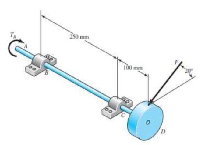
The rotating solid steel shaft is simply supported by bearings at points B and C and is driven by a gear (not shown) which meshes with the spur gear at D. which has a 150-mm pitch diameter. The force F from the drive gear acts at a pressure angle of 20°. The shaft transmits a torque to point A of TA = 340 N · m. The shaft is machined from steel with Sy = 420 MPa and Sut = 560 MPa. Using a factor of safety of 2.5, determine the minimum allowable diameter of the 250-mm section of the shaft based on (a) a static yield analysis using the distortion energy theory and (b) a fatigue-failure analysis. Assume sharp fillet radii at the bearing shoulders for estimating stress-concentration factors.

Trending nowThis is a popular solution!

Chapter 7 Solutions
SHIGLEY'S MECH.ENGIN....(LOOSE)>CUSTOM<


- A motor driving a solid circular steel shaft with diameter d = 1.5 in, transmits 50 hp to a gear at B, The allowable shear stress in the steel is 6000 psi. Calculate the required speed of rotation (number of revolutions per minute) so that the shear stress in the shaft does not exceed the allowable limit.arrow_forwardWhat is the maximum power that can be delivered by a hollow propeller shaft (outside diameter 50 mm, inside diameter 40 mm, and shear modulus of elasticity 80 GPa) turning at 600 rpm if the allowable shear stress is 100 MPa and the allowable rate of twist is 3.0°/m?arrow_forwardA solid circular shaft AB of diameter d is fixed against rotation at both ends (sec figure), A circular disk is attached to the shaft at the location shown. What is the largest permissible angle of rotation 0max of the disk if the allowable shear stress in the shaft is Tallow? [Assume that a >b. Also, use Eqs. (3-50a and b) of Example 3-9 to obtain the reactive torques.]arrow_forward
- Repeat Problem 11.2-3 assuming that R= 10 kN · m/rad and L = 2 m.arrow_forwardThe shaft consists of a 3-in diameter aluminum segment that is rigidly joined to a 2-in diameter steel segment. The ends of the shaft are attached to rigid supports, Calculate the angle of twist developed at the interface of the two segments when the torque T = 50 kip٠in is applied. Use G = 4×10⁶ psi for aluminum and G = 12×106 psi for steel.arrow_forwardA 39 in. tubular shaft is in torsion under a torque of 34 lb-in.. Its cross-section shown below as diameter d1 = 3.2 in., diameter d2 = 1.4 in. If it is a soft tube, and G = 315 psi, calculate the angle of twist of the shaft: _____ O (degrees). Pay attention to units, and calculate your answer to one decimal place.arrow_forward
- Determine the diameter of a solid steel shaft which will transmit 112.5 kW at 200 rpm. Also determine the length of the shaft if the twist must not exceed 1.5o over the entire length. The maximum shear stress is limited to 55 N/mm2. Take the value of modulus of rigidity = 8 x 10⁴ N/mm2.arrow_forwardThe two solid steel shafts shown in the figure are connected together using gear wheels. The length of the CD shaft is Lcd=2 m and the length of the AB shaft is LAB= 1.5 m. The radius of gear C is rc=45 mm and the radius of gear B is rB= 90 mm. The CD and AB shafts rotate freely in the bearings on which they are supported. Also, shaft AB is fixed at point A. Each shaft has a diameter of 20 mm and a shear modulus of G=65 GPa. When a torque of T= 450 N.m is applied to the CD shaft from the D end;a) Calculate the torsion angle on shaft AB. (Write your result in radians.)b) Calculate the total rotation (torsion angle) of the D end of the CD shaft. (Write your result in radians.)arrow_forwardA motor driving a solid circular steel shaft transmits 85 horsepower to a gear at point B (see sketch below). The allowable shear stress in the steel shaft is 6000 pounds per square inch. Determine: The minimum diameter d of the shaft if the shaft is operated at 1350 rpm (revolutions per minute). If the shaft transmits the same power (85 horsepower) at 3500 rpm, will the shaft diameter be larger or smaller than the required diameter of part 1.arrow_forward
- In the gear system shown in the figure, the motor applies a torque of 231 N-m to the gear at A. A torque of TC = 440 N-m is removed from the shaft at gear C, and the remaining torque is removed at gear D. Segments (1) and (2) are solid 38-mm-diameter steel (G = 80 GPa) shafts, and the bearings shown allow free rotation of the shaft. Assume DA = 110 mm, DB = 370 mm, L1 = 1.7 m, and L2 = 1.1 m. Calculate the rotation angle of gear D relative to gear B. Express your answer in radian rounded to the nearest thousandths.arrow_forwardA motor driving a solid circular steel shaftwith diameter d = 1.5 in. transmits 50 hp to a gear atB. The allowable shear stress in the steel is 6000 psi.Calculate the required speed of rotation (number ofrevolutions per minute) so that the shear stress in theshaft does not exceed the allowable limit.arrow_forwardA 30 in. tubular shaft is in torsion under torque 33 lb-in.. Its cross section shown below with diameter d1 = 3.2 in., diameter d2 = 1.0 in. Calculate shear stress at point B shown above: _____ psi. Calculate your answer to one decimal place.arrow_forward
 Mechanics of Materials (MindTap Course List)Mechanical EngineeringISBN:9781337093347Author:Barry J. Goodno, James M. GerePublisher:Cengage Learning