
Concept explainers
Videos
For the problem specified in the table, build upon the results of the original problem to obtain a preliminary design of the shaft by performing the following tasks.
(a) Sketch a general shaft layout, including means to locate the components and to transmit the torque. Estimates for the component widths are acceptable at this point.
(b) Specify a suitable material for the shaft.
(c) Determine critical diameters of the shaft based on infinite fatigue life with a design factor of 1.5. Cheek for yielding.
(d) Make any other dimensional decisions necessary to specify all diameters and axial dimensions. Sketch the shaft to scale, showing all proposed dimensions.
(e) Cheek the deflections at the gears, and the slopes at the gears and the bearings for satisfaction of the recommended limits in Table 7–2. Assume the deflections for any pulleys are not likely to be critical. If any of the deflections exceed the recommended limits, make appropriate changes to bring them all within the limits.
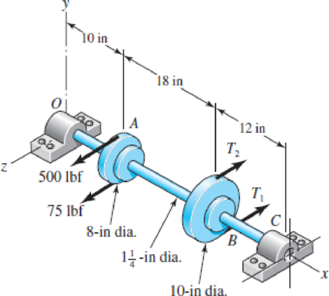
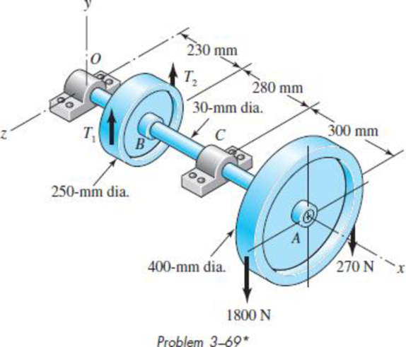
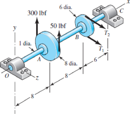
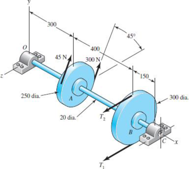
3–68* to 3–71* A countershaft carrying two V-belt pulleys is shown in the figure. Pulley A receives power from a motor through a belt with the belt tensions shown. The power is transmitted through the shaft and delivered to the belt on pulley B. Assume the belt tension on the loose side at B is 15 percent of the tension on the tight side.
(a) Determine the tensions in the belt on pulley B, assuming the shaft is running at a constant speed.
(b) Find the magnitudes of the bearing reaction forces, assuming the bearings act as simple supports.
(c) Draw shear-force and bending-moment diagrams for the shaft. If needed, make one set for the horizontal plane and another set for the vertical plane.
(d) At the point of maximum bending moment, determine the bending stress and the torsional shear stress.
(e) At the point of maximum bending moment, determine the principal stresses and the maximum shear stress.
Problem 3–68*
Problem 3–69*
Problem 3–70*
Dimensions in inches.
Problem 3–71*
Dimensions in inches.
Want to see the full answer?
Check out a sample textbook solution
Chapter 7 Solutions
SHIGLEY'S MECH.ENGIN....(LOOSE)>CUSTOM<


- The polar modulus for a solid shaft of 40 mm diameter isarrow_forwardA shaft is designed to transmit power of 100 kW at 180 rpm. The allowable shear stress is 50MPa and modulus of rigidity of 80 GPa. The angle of twist is not to exceed to 1° in 4-meter length A. Calculate the diameter of the shaft in inches. B.If the shaft in A is to be fitted to a hub with material SAE 0105 and fit classification of FN3, what will be the maximum and minimum stresses based on the interference of metal.arrow_forwardA solid 1.2 in. diameter shaft is used to synchronize multiple mechanisms in a manufacturing plant. The torque delivered by the shaft is 3200 lb·in. What horsepower must be delivered to the shaft to maintain a shaft speed of 690 rpm? What is the maximum shear stress developed in the shaft?arrow_forward
- a single-start, square-threaded power screw with the following parameters: PARTS A - D circle final answers for each part A -  A weight of 1500 N must be lifted. What is the total required torque necessary to lift this weight? Give your answer in units of N m. Part B - if the available power to drive the screw is 1,011 Watts, determine the fastest speed at which the weight can rise. Give your answer in units of mm/s, Part C - The efficiency of the preceding power screw (expressed as a number between 0 and 1, not as a percentage) is ? Part D - Suppose a high-quality thrust bearing was used to eliminate the collar friction. The efficiency of the screw would now be?arrow_forwardtopic: torsion in circular shafts Determine the torsion on the rigid supports and the maximum shearing stress developed in each segment. Provide a torque diagram, strictly follow instructed sign convention, and start from left to rightarrow_forwardWhat is the minimum diameter in meter of a solid steel shaft that will not twist through more than 3˚ in 6 meter length, when subjected to a torque of 14 kN m. Use G of 83 Gpa.arrow_forward
- Design a hallow shaft (Diameter and length) that develops 80 kW of power while rotating at a speed of 4000 rpm. The design constrains are as under:The angle of twist not to exceed 0.200Shear stress is not to exceed 480 MN/m2The outer diameter is to be twice the inner diameter. The shaft length is to be three times the outer diameter. Modulus of rigidity = 79 GN/m2.arrow_forwardA single-threaded power screw of square form is to raise a load of 90KN at the rate of 360mm/min. Other data are as follows: Nominal Diameter of screw = 36mm Pitch = 6mm Coefficient of thread friction = 0.1 Coefficient of collar friction = 0.08 Friction radius at collar= 30mm Determine the power input to the screw in kilowatts.arrow_forwardA solid shaft subjected to compressive force of 1000 lb and carries a 5000 lb load at the center of the shaft. If the shaft length is 6 ft, what is the required shaft diameter for a safe working stress of 40,000 psi?arrow_forward
- Design a hollow circular steel shaft to transmit an applied torque of 360,000 in-lbs. The allowable shear stress is 6,000 psi and the inside diameter is to be 0.6 times the outside diameter. Not sure how to solve this problem, please walk me through the process step-by-step and write clearly. Thanks in advance.arrow_forwardSelect the diameter for a solid steel shaft that is to transmit 60 HP at 850 rpm without exceeding an allowable shear stress of 7,000 psi. Answer: 1.48 inches. I do not know how to solve this problem. Please help me solve for this answer step-by-step. Thank you in advance.arrow_forwardIn drilling a deep oil well the drill shaft, consisting of sections of “drill rod”, is powered from the top, while the load or counter torque is taken off at the bottom. The drill hole is 3 1/2 miles deep. Assuming a solid drill rod of circular cross section and 1 in. diameter, designed to a working shear stress of 5,000 psi, turning at 700 rpm, calculate (a) The wind-up, i.e. the twist angle between the top and bottom. (b) The horsepower of the driving motor. (c) State all assumptions, and comment on the results. What other considerations may have to be taken into account in using this drill? NOTE: The shear modulus of steel may be taken as 12 x 106 psi. Also 1 mile = 5,280 ft.arrow_forward
 Elements Of ElectromagneticsMechanical EngineeringISBN:9780190698614Author:Sadiku, Matthew N. O.Publisher:Oxford University Press
 Mechanics of Materials (10th Edition)Mechanical EngineeringISBN:9780134319650Author:Russell C. HibbelerPublisher:PEARSON
 Thermodynamics: An Engineering ApproachMechanical EngineeringISBN:9781259822674Author:Yunus A. Cengel Dr., Michael A. BolesPublisher:McGraw-Hill Education
 Control Systems EngineeringMechanical EngineeringISBN:9781118170519Author:Norman S. NisePublisher:WILEY
 Mechanics of Materials (MindTap Course List)Mechanical EngineeringISBN:9781337093347Author:Barry J. Goodno, James M. GerePublisher:Cengage Learning
 Engineering Mechanics: StaticsMechanical EngineeringISBN:9781118807330Author:James L. Meriam, L. G. Kraige, J. N. BoltonPublisher:WILEY