
SHIGLEY'S MECH.ENGIN....(LOOSE)>CUSTOM<
10th Edition
ISBN: 9781260163155
Author: BUDYNAS
Publisher: MCG CUSTOM
expand_more
expand_more
format_list_bulleted
Concept explainers
Videos
Textbook Question
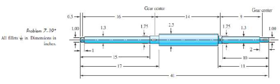
Chapter 7, Problem 19P
The shaft shown in the figure is proposed for the application defined in Prob. 3–72, p. 152. The material is AISI 1018 cold-drawn steel. The gears seat against the shoulders, and have hubs with setscrews to lock them in place. The effective centers of the gears for force transmission are shown. The keyseats are cut with standard endmills. The bearings are press-fit against the shoulders. Determine the minimum fatigue factor of safety using the DE-Gerber fatigue criterion.
Expert Solution & Answer
Want to see the full answer?
Check out a sample textbook solution
Students have asked these similar questions
A 15 kW and 1200 r.p.m. motor drives a compressor at 300
r.p.m. through a pair of spur gears having
20° stub teeth. The centre to centre distance between the shafts
is 400 mm. The motor pinion is made
of forged steel having an allowable static stress as 210 MPa,
while the gear is made of cast steel
having allowable static stress as 140 MPa. Assuming that the
drive operates 8 to 10 hours per day
under light shock conditions, find from the standpoint of
strength,
1. Module; 2. Face width and 3. Number of teeth and pitch circle
diameter of each gear.
Check the gears thus designed from the consideration of wear.
The surface endurance limit may be
taken as 700 MPa
A 15 kW and 1200 r.p.m. motor drives a compressor at 300 r.p.m. through a pair of spur gears having 20° stub teeth. The centre to centre distance between the shafts is 400 mm. The motor pinion is made of forged steel having an allowable static stress as 210 MPa, while the gear is made of cast steel having allowable static stress as 140 MPa. Assuming that the drive operates 8 to 10 hours per day under light shock conditions, find from the standpoint of strength, 1. Module; 2. Face width and 3. Number of teeth and pitch circle diameter of each gear. Check the gears thus designed from the consideration of wear. The surface endurance limit may be taken as 700 MP
The solid steel rotating shaft in the figure is supported at B and C, and is driven by a gear, not seen, which is linked to spur gear D which has a pitch diameter of 150 mm. The drive gear force F acts at a pressure angle of 20 degrees. The shaft transmits a torque to point A of Ta-350 N.m. The properties of machined steel shaft are Sy-420 MPa and Sut-560MPa. Use a safety factor of 2.5 and determine the minimum allowable diameter in section B and C. Assume sharp felt radii at the bearing shoulders to estimate the stress concentration factors.Explain.
Chapter 7 Solutions
SHIGLEY'S MECH.ENGIN....(LOOSE)>CUSTOM<
Ch. 7 - A shaft is loaded in bending and torsion such that...Ch. 7 - The section of shaft shown in the figure is to be...Ch. 7 - The rotating solid steel shaft is simply supported...Ch. 7 - A geared industrial roll shown in the figure is...Ch. 7 - Design a shaft for the situation of the industrial...Ch. 7 - The figure shows a proposed design for the...Ch. 7 - For the problem specified in the table, build upon...Ch. 7 - Prob. 8PCh. 7 - For the problem specified in the table, build upon...Ch. 7 - For the problem specified in the table, build upon...
Ch. 7 - In the figure is a proposed shaft design to be...Ch. 7 - The shaft shown in the figure is proposed for the...Ch. 7 - Prob. 20PCh. 7 - The shaft shown in the figure is proposed for the...Ch. 7 - Prob. 25PCh. 7 - Prob. 26PCh. 7 - Prob. 27PCh. 7 - A 25-mm-diameter uniform steel shaft is 600 mm...Ch. 7 - Prob. 29PCh. 7 - Compare Eq. (727) for the angular frequency of a...Ch. 7 - Prob. 31PCh. 7 - The steel shaft shown in the figure carries a...Ch. 7 - A transverse drilled and reamed hole can be used...Ch. 7 - Prob. 34PCh. 7 - The shaft shown in Prob. 721 is proposed for the...Ch. 7 - A guide pin is required to align the assembly of a...Ch. 7 - Prob. 37PCh. 7 - Prob. 38PCh. 7 - Prob. 39PCh. 7 - A ball bearing has been selected with the bore...Ch. 7 - Prob. 41PCh. 7 - A gear and shaft with nominal diameter of 35 mm...
Knowledge Booster


Learn more about
Need a deep-dive on the concept behind this application? Look no further. Learn more about this topic, mechanical-engineering and related others by exploring similar questions and additional content below.Similar questions
- In the fabric dye-printing system given in the figure, the motion is transmitted from the electric motor to the drum of the machine. There is a two-stage reducer in between. Number of teeth of gears z1=17; z2=85; z3=18; z4=72; The efficiency of a pair of gears is given as na=0.97 and the efficiency of each of the gearbox shafts and lower bearing pairs to the drum bearing is given as n=0.97. The diameter of the drum will be D=200 mm, the fabric speed will be v=1 m/s and the pulling force required to activate the band will be taken as F-2000 N. a) Find the number of revolutions of the engine. b) Find the required engine power.arrow_forwardA compound shaft drives three gears, as shown. Segments (1) and (2) of the compound shaft are hollow bronze [G = 6,500 ksi] tubes, which have an outside diameter of 2.40 in. and a wall thickness of 0.1375 in. Segments (3) and (4) are solid 1.00-in.-diameter steel [G = 11,500 ksi] shafts. The shaft lengths are L1 = 58 in., L2 = 16 in., L3 = 16 in., and L4 = 28 in. The torques applied to the shafts have magnitudes of TB = 970 lb·ft, TD = 430 lb·ft, and TE = 170 lb·ft, acting in the directions shown. The bearings shown allow the shaft to turn freely. Using the sign convention presented in Section 6.6., calculate: (a) the magnitude of the maximum shear stress in the compound shaft. (b) the rotation angle of flange C with respect to flange A. (c) the rotation angle of gear E with respect to flange A.arrow_forwardThe motor shown in the figure supplies 16.5 kW at 1540 rpm at A. Shafts (1) and (2) are each solid 28 mm diameter shafts. Shaft (1) is made of an aluminum alloy [ G=26 GPa], and shaft (2) is made of bronze [ G=45 GPa]. The shaft lengths are L1=3.3m and L2=2.9m, respectively. Gear B has 56 teeth, and gear C has 97 teeth. The bearings shown permit free rotation of the shafts. Determine: the rotation angle of gear D with respect to flange A. [Answer φD/A = 0.314 rad]arrow_forward
- A single stage spur gear gearbox has a module of 1.5mm and an input speed of 1500.p.m. and a pinion with 15 teeth. The overall ratio of the gearbox is 6:1 and the gearbox is transmitting a power of 6000W. If the factor of safetv is to be reduced to an absolute minimum acceptable value and the gears are to be made from a material with a Yield stress of 540 MPa, what is the face width of the gears (in mm) Express your answer in the form 21.00 ie with two decimal place an no unitsarrow_forwardThe shaft shown in the figure is machined from AISI 1040 CD steel. The shaft rotates at 1600 rpm and is supported in rolling bearings at A and B. The applied forces are F1 = 1600 lbf and F2 = 640 lbf. A steady torque of 1600 lbf·in is being transmitted through the shaft between the points of application of the forces.arrow_forwardA 15 kW and 1200 motor drives a compressor at 300 a pair of spur gears having . The center-to-center distance between the shafts is 400 . The motor pinion is made of forged steel having an allowable static stress as 210 MPa, while the gear is made of cast steel having allowable static stress as 140 MPa . Assuming that the drive operates 8 to 10 hours per day under light conditions , find from the standpoint of strength Module , 2. Fare and 3. Number of teeth and pitch circle diameter of each gear 2. Check the gears thus designed from the consideration of Static tooth load or endurance strength of the tooth flexural endurance limil (sigma_{\epsilon}) may be taken as 400 MPa 3. Check the gears thus designed from the consideration of wear surface endurance limit ( sigma epsilon x ) may be taken 700 MPa b ^ pi ( 6.154 - 0512/pi; F_{N}arrow_forward
- A short stub shaft, made of SAE 1035, as rolled, receivers 30 hp at 300 rpm via a 12-in. spur gear, the power being delivered to another shaft through a flexible coupling. The gear is keyed (profile keyway) midway between the bearings. The pressure angle of the gear teeth 20o, N = 1.5 based on the octahedral shear stress theory with varying stresses. (a) Neglecting the radial component R of the tooth load W , determine the shaft diameter. (b) Considering both the tangential and the radial components, compute the shaft diameters. (c) Is the difference in the results of the parts (a) and (b) enough to change your choice of the shaft size?arrow_forwardThe intermediate shaft of a two-stage gearbox is given in the figure. P = 4 kW power is transmitted at n = 150 rpm with the help of two helical gears on the shaft.The forces acting on the gears are given as Ft1 = 5092 N, Fr1 = 1972 N, Fa1 = 1853 N, Ft2 = 2546 N, Fr2 = 986 N, Fa2 = 926 N. Diameter of small helical gear d1 = 100 mm, largethe diameter of the gear is d2 = 200 mm. Shaft material yield strength 335 MPa, tensile strength 600 MPa, Kç = 1.95, ka = 0.895, kb = 0.90 and safety coefficient = 1.4now thatarrow_forwardA 15KW and 1200r.p.m motor drives a compressor at 300r.p.m through a pair of spur gears having 20° stub teeth .the centre to centre distance between the shafts is 400mm.the motor pinion is made to forged steel having an allowable static stress 210MPa while the gear is made of cast steel having an allowable static stress as 140MPa.Assuming that the drive operates 8 to 10 hours per day under light shock conditions,find from the standpoint of strength (a) Module;(b)face width and (c)number of teeth an pitch circle diameter of each gear.check the gears thus designed from the consideration of wear .the surface endurance limit may be taken as 700MPa.arrow_forward
- 13–31 Shaft a in the figure has a power input of 75 kW at a speed of 1000 rev/min in the counterclockwise direction. The gears have a module of 5 mm and a 20° pressure angle. Gear 3 is an idler.(a) Find the force F3b that gear 3 exerts against shaft b.arrow_forwardA pair of 20º full depth involute teeth bevel gears connect two shafts at right angles having velocity ratio 3 : 1. The gear is made of cast iron having allowable static stress as 70 MPa and the 20teeth pinion is of steel with allowable static stress as 100 MPa and 200BHN. The pinion works at 750 r.p.m. Determine the maximum power can be transmitted by the gears if the module is 10mm. Kf=1.4arrow_forwardA gear train is composed of four helical gears with the three shaft axes in a single plane, as shown in the figure. The gears have a normal pressure angle of 20 and a 30 helix angle. Gear is the driver, and is rotating counterclockwise as viewed from the top. Shaft b is an idler and the transmitted load from gear 2 to gear 3 is 500 Ibf. The gears on shaft b both have a normal diametral pitch of 7 teeth/in and have 54 and 14 teeth, respectively. Find the forces exerted by gears 3 and 4 on shaft barrow_forward
arrow_back_ios
SEE MORE QUESTIONS
arrow_forward_ios
Recommended textbooks for you
 Mechanics of Materials (MindTap Course List)Mechanical EngineeringISBN:9781337093347Author:Barry J. Goodno, James M. GerePublisher:Cengage Learning
Mechanics of Materials (MindTap Course List)
Mechanical Engineering
ISBN:9781337093347
Author:Barry J. Goodno, James M. Gere
Publisher:Cengage Learning
Everything About COMBINED LOADING in 10 Minutes! Mechanics of Materials; Author: Less Boring Lectures;https://www.youtube.com/watch?v=N-PlI900hSg;License: Standard youtube license