
Videos
Over a certain range of air speeds, V, the lift, FL, produced by a model of a complete aircraft in a wind tunnel depends on the air speed, air density, ρ, and a characteristic length (the wing base chord length, c = 150 mm). The following experimental data is obtained for air at standard atmospheric conditions:
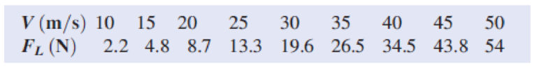
Plot the lift versus speed curve. Generate and plot data for the lift produced by the prototype, which has a wing base chord length of 5 m, over a speed range of 75 m/s to 250 m/s.
Want to see the full answer?
Check out a sample textbook solution
Chapter 7 Solutions
Fox and McDonald's Introduction to Fluid Mechanics
Additional Engineering Textbook Solutions
Mechanics of Materials
Engineering Mechanics: Statics
Fundamentals Of Thermodynamics
Mechanics of Materials (10th Edition)
Engineering Mechanics: Statics
Thinking Like an Engineer: An Active Learning Approach (4th Edition)


- a test tank will be used to measure the drag of a scale model ship 0.8 m long. This model bears full resemblance to a 40 m long prototype ship that was designed to sail at a speed of 10 m / s. a) model speed b) the ratio between model and prototype drag windows c) a ratio between the powers needed to overcome the drag of the model and the prototype take the number of froud into account in your analysis.arrow_forwarda test tank will be used to measure the drag of a scale model ship 0.8 m long. This model bears full resemblance to a 40 m long prototype ship that was designed to sail at a speed of 10 m / s. Evaluate: a) the speed of the modelb) the ratio between the drag forces of the model and the prototypec) the relationship between the powers needed to overcome the drag of the model and the prototype take the number of froud into account in your analysis.arrow_forwardA model of the Airbus 320 is tested in a wind tunnel using air at standard conditions. If the tunnel airspeed is 50m/s, calculate the water speed if the same model is to be tested in a water tunnel atdynamically similar conditions. Take mair=1.73 x 10⁻⁵Pa.s, mwater=10-3Pa.s, rair=1.225kg/m3 andrwater=1000 kg/m3.arrow_forward
- A 1:10 scale model study of a torpedo is proposed. Prototype speeds of 90 km/hare to be studied. Should a wind tunnel or a water facility be used?arrow_forwardA hovercraft weighs M = 1500 kg and hovels without changing altitude. The exit flow exhausts to atmospheric pressure at sea-level. The flow is steady, incompressible and uniform properties can be assumed on all control surfaces. Assume air density = 122 kg/m^3.arrow_forwardA one-fiftieth-scale model of a military airplane is tested at1020 m/s in a wind tunnel at sea-level conditions. Themodel wing area is 180 cm 2 . The angle of attack is 3 ° . If themeasured model lift is 860 N, what is the prototype lift,using Mach number scaling, when it flies at 10,000 m standardaltitude under dynamically similar conditions? Note:Be careful with the area scaling.arrow_forward
- Assume an inviscid, incompressible flow. Also, standard sea level density and pressure are 1.23 kg/m3 (0.002377 slug/ft3) and 1.01 × 10⁵ N/m2(2116 lb/ft2), respectively. Consider the flow field over a circular cylinder mounted perpendicular tothe flow in the test section of a low-speed subsonic wind tunnel. Atstandard sea level conditions, if the flow velocity at some region of theflow field exceeds about 250 mi/h, compressibility begins to have an effectin that region. Calculate the velocity of the flow in the test section of thewind tunnel above which compressibility effects begin to become important, i.e., above which we cannot accurately assume totallyincompressible flow over the cylinder for the wind tunnel tests.arrow_forwardA student needs to measure the drag on a prototype of characteristicdimension d p moving at velocity U p in air at standardatmospheric conditions. He constructs a model ofcharacteristic dimension d m , such that the ratio d p / d m issome factor f . He then measures the drag on the model atdynamically similar conditions (also with air at standardatmospheric conditions). The student claims that the dragforce on the prototype will be identical to that measured onthe model. Is this claim correct? Explain.arrow_forwardConsider a business jet with the following characteristics:• Weight: 25208 kg• Wing area: 53.5 m^2• Wing span: 21.7 m• Cruise altitude: 10,000 m • Drag polar parameters (cruise): CD0 = 0.015, K= 0.08• Engine: Number of engines: 2 Max. thrust (at sea level, for 1 engine): 45 kN TSFC (for 1 engine): 0.41 1/h Calculate the velocity for minimum thrust required using the analytical expression (formula)? Calculate the velocity for minimum power required using the analytical expression (formula).? Calculate the maximum velocity using one possible graphical approach, and analytical approach?arrow_forward
- 1) Calculate the drag force (unit: N) of a sphere particle in 20°C water. Know the diameter of the particle = 1 cm; the Reynolds number of water = 1; dynamic viscosity of 20°C water = 0.001 kg/ms; velocity of the particle = 0.02 m/s. 2) When calculate the lift coefficient, the area A in the equation is: a) surface area b) planform area c) cross-sectional area d) frontal area 3) The sum of the components of the pressure and wall shear forces (a) in the flow direction is called ____ and (b) in the normal direction is called ____. a) Friction, Pressure b) Lift, Drag c) Pressure, Friction d) Drag, Liftarrow_forwardProblem 5Given: A prototype ship is 50 m long and designed for a cruising speed of 10 m/s. The drag is to be simulated by a 1-m-long model that will be towed in a towing tank.Required: Using Froude scaling, determine the tow speed and the ratio of the model to prototype drag and power (i.e. Vm/Vp and Pm/Pp . Recall: Power=Force*Velocityarrow_forwardConsider a Boeing 747 airliner cruising at a velocity of 550 mi/h at a standard altitude of 38,000 ft, where the freestream pressure and temperature are 432.6 lb/ft2 and 390◦R, respectively. A one-fiftieth scale model of the 747 is tested in a wind tunnel where the temperature is 430◦R. In addition to the information given in above, for this airplane the zero-lift angle of attack is −2◦, the lift slope of the airfoil section is 0.1 per degree, the lift efficiency factor τ = 0.04, and the wing aspect ratio is 7.96. At the cruising condition treated given, calculate the angle of attack of the airplane.arrow_forward
 Elements Of ElectromagneticsMechanical EngineeringISBN:9780190698614Author:Sadiku, Matthew N. O.Publisher:Oxford University Press
 Mechanics of Materials (10th Edition)Mechanical EngineeringISBN:9780134319650Author:Russell C. HibbelerPublisher:PEARSON
 Thermodynamics: An Engineering ApproachMechanical EngineeringISBN:9781259822674Author:Yunus A. Cengel Dr., Michael A. BolesPublisher:McGraw-Hill Education
 Control Systems EngineeringMechanical EngineeringISBN:9781118170519Author:Norman S. NisePublisher:WILEY
 Mechanics of Materials (MindTap Course List)Mechanical EngineeringISBN:9781337093347Author:Barry J. Goodno, James M. GerePublisher:Cengage Learning
 Engineering Mechanics: StaticsMechanical EngineeringISBN:9781118807330Author:James L. Meriam, L. G. Kraige, J. N. BoltonPublisher:WILEY