
Concept explainers
Videos
For the beam shown, draw the shear and bending-moment diagrams, and determine the magnitude and location of the maximum absolute value of the bending moment, knowing that (a) M = 0, (b) M = 24 kip-ft.
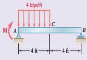
Fig. P7.161
(a)
Plot the shear force and bending moment diagram for the beam.
Find the magnitude and location of the maximum absolute value of the bending moment.
Answer to Problem 7.161RP
The location and magnitude of the maximum absolute bending moment is
Explanation of Solution
Given information:
The moment applied at A is
Calculation:
Show the free-body diagram of the entire beam as in Figure 1.
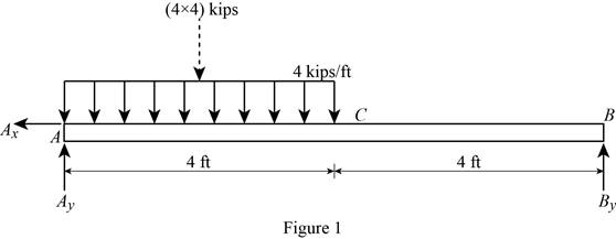
Find the vertical reaction at point B by taking moment about point A.
Find the vertical reaction at point A by reoslving the vertical component of forces.
Resolve the horizontal component of forces.
Consider the section AC:
Consider a section at a distance x from left end A.
Show the free-body diagram of the section as in Figure 2.
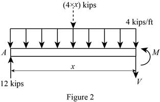
Resolve the vertical component of forces.
Take moment about the section.
At
Substitute 0 for x in Equation (1).
Substitute 0 for x in Equation (2).
At
Substitute 4 ft for x in Equation (1).
Substitute 4 ft for x in Equation (2).
Consider the section CB:
Show the free-body diagram of the section as in Figure 3.
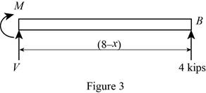
Resolve the vertical component of forces.
Take moment about the section.
At
Substitute 4 ft for x in Equation (3).
At
Substitute 8 ft for x in Equation (3).
Tabulate the shear force values as in Table 1.
| Location, x ft | Shear force, kips |
| 0 | 12 |
| 4 | –4 |
| 8 | –4 |
Plot the shear force diagram as in Figure 4.
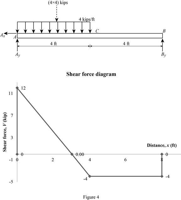
The maximum bending moment occurs where the shear force changes sign.
Refer to the Figure 4, the shear force changes in the section AC.
Substitute 0 for V in Equation (1).
Substitute 3 ft for x in Equaiton (2).
Tabulate the bending moment values as in Table 2.
| Location, x ft | Bending moment, kips-ft |
| 0 | 0 |
| 3 | 18 |
| 4 | 16 |
| 8 | 0 |
Plot the bending moment values as in Figure 5.
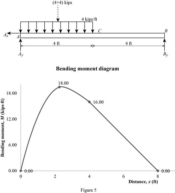
Therefore, the location and magnitude of the maximum absolute bending moment is
(b)
Plot the shear force and bending moment diagram for the beam.
Find the magnitude and location of the maximum absolute value of the bending moment.
Answer to Problem 7.161RP
The location and magnitude of the maximum absolute bending moment is
Explanation of Solution
Given information:
The moment applied at A is
Calculation:
Show the free-body diagram of the entire beam as in Figure 6.
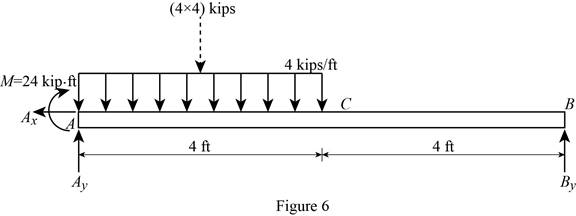
Find the vertical reaction at point B by taking moment about point A.
Find the vertical reaction at point A by reoslving the vertical component of forces.
Resolve the horizontal component of forces.
Consider the section AC:
Consider a section at a distance x from left end A.
Show the free-body diagram of the section as in Figure 7.
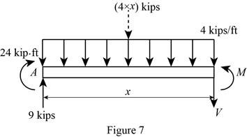
Resolve the vertical component of forces.
Take moment about the section.
At
Substitute 0 for x in Equation (4).
Substitute 0 for x in Equation (5).
At
Substitute 4 ft for x in Equation (4).
Substitute 4 ft for x in Equation (5).
Consider the section CB:
Show the free-body diagram of the section as in Figure 8.
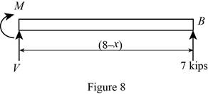
Resolve the vertical component of forces.
Take moment about the section.
At
Substitute 4 ft for x in Equation (6).
At
Substitute 8 ft for x in Equation (6).
Tabulate the shear force values as in Table 3.
| Location, x ft | Shear force, kips |
| 0 | 9 |
| 4 | –7 |
| 8 | –7 |
Plot the shear force diagram as in Figure 9.
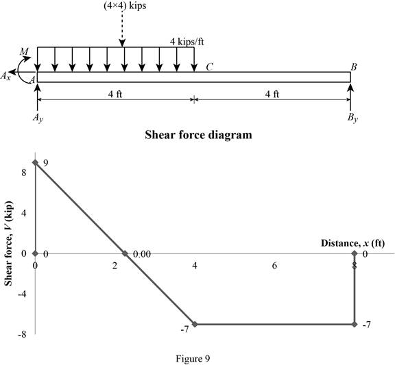
The maximum bending moment occurs where the shear force changes sign.
Refer to the Figure 4, the shear force changes in the section AC.
Substitute 0 for V in Equation (4).
Substitute 2.25 ft for x in Equaiton (5).
Tabulate the bending moment values as in Table 4.
| Location, x ft | Bending moment, kips-ft |
| 0 | 0 |
| 2.25 | 34.125 |
| 4 | 28 |
| 8 | 0 |
Plot the bending moment values as in Figure 10.
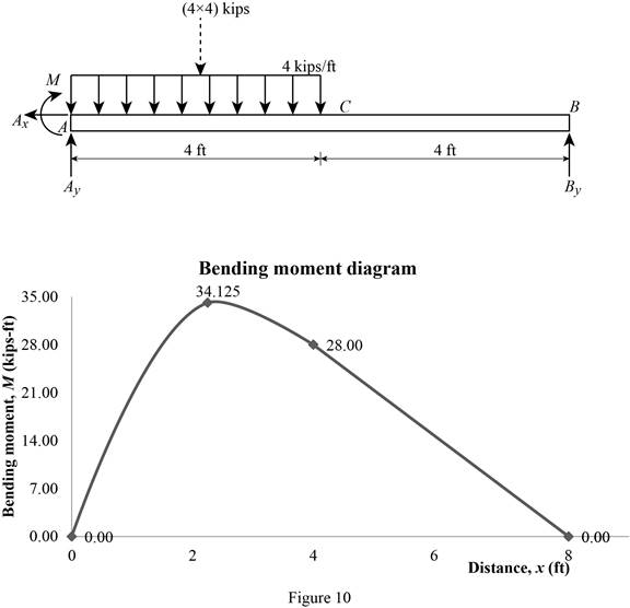
Therefore, the location and magnitude of the maximum absolute bending moment is
Want to see more full solutions like this?
Chapter 7 Solutions
Package: Loose Leaf for Vector Mechanics for Engineers: Statics with 1 Semester Connect Access Card


- Knowing that P= 480 N,Q=320N determine (a) the distance a for which the absolute value of the bending moment in the beam is as small as possible, (b) the corresponding maximum normal stress due to bending.arrow_forwardTwo small channel sections DF and EH have been welded to the uniform beam AB of weight W = 3 kN to form the rigid structural member shown. This member is being lifted by two cables attached at D and E . Knowing that 0= 30° and neglecting the weight of the channel sections, (a) draw the shear and bending-moment diagrams for beam AB, (b) determine the maximum absolute values of the shear and bending moment in the beam.arrow_forwardKnowing that P=Q= 480 N, determine (a) the distance a for which the absolute value of the bending moment in the beam is as small as possible, (b) the corresponding maximum normal stress due to bending.arrow_forward
- Provided that the bending formation of a straight member is small and within elastic range, and neutral axis is denoted as z axis as shown below, the normal stress, σx ( fb in textbook) developed by bending moment on cross section will not vary along z direction. True Falsearrow_forwardDraw the shear and bending-moment diagrams for the beam and loading shown, and determine the maximum absolute value (a) of the shear, (b) of the bending momentarrow_forwardA) The four cross sections shown have different characteristics when subjected to a vertical shear force. Which of the four geometries shown has the largest value for the moment of the area, Q, about the neutral axis? B) Which of the four geometries shown has the smallest value for its moment of inertia about the x axis? C) Given that all four geometries are subjected to the same vertical shear force V, which of the four has the smallest value for the maximum shear stress?arrow_forward
- Problem 03: Draw the shear and bending-moment diagrams for the beam and loading shown, and determine the maximum absolute value (a) of the shear, (b) of the bending moment.arrow_forwardFor the beam and loading shown, determine the absolute values of the shear and bending moment at 2.5 m to the left of point B.arrow_forwardA beam is carrying a moment M as indicated. The cross section of the beam is symmetric about the z axis. The dimensions of the cross section and the location of the centroid (point C) are shown. Knowing that Iy = 280,000 mm4, Iz = 150,000 mm4, and M = 400,000 + UV in N.mm, where UV is 21(a) Calculate the components of the bending moment on the y and z axes, Myand Mz.(b) Identify which point at the cross section has the largest tensile stress, and which point at the cross section has the largest compressive stress.(c) Calculate the maximum tensile stress and the maximum compressive stress in the cross sectionarrow_forward
- Knowing that W = 12 kN, draw the shear and bending-moment diagrams for beam AB and determine the maximum normal stress due to bending.arrow_forwardDraw the shear and bending-moment diagrams for the beam and loading shown, and determine the maximum absolute value (a) of the shear, (b) of the bendingarrow_forwardA 12-m simply supported overhang beam is supported at x = 0 and x = 10m. The overhanging portion is from x = 10m to x = 12m (the overhang portion is 2m). Two equal wheel loads of 20kN each, separated by 2m roll as a unit across the 12-m span. Determine the maximum shear developed in the span.arrow_forward
 Elements Of ElectromagneticsMechanical EngineeringISBN:9780190698614Author:Sadiku, Matthew N. O.Publisher:Oxford University Press
 Mechanics of Materials (10th Edition)Mechanical EngineeringISBN:9780134319650Author:Russell C. HibbelerPublisher:PEARSON
 Thermodynamics: An Engineering ApproachMechanical EngineeringISBN:9781259822674Author:Yunus A. Cengel Dr., Michael A. BolesPublisher:McGraw-Hill Education
 Control Systems EngineeringMechanical EngineeringISBN:9781118170519Author:Norman S. NisePublisher:WILEY
 Mechanics of Materials (MindTap Course List)Mechanical EngineeringISBN:9781337093347Author:Barry J. Goodno, James M. GerePublisher:Cengage Learning
 Engineering Mechanics: StaticsMechanical EngineeringISBN:9781118807330Author:James L. Meriam, L. G. Kraige, J. N. BoltonPublisher:WILEY