
INTERNATIONAL EDITION---Engineering Mechanics: Statics, 14th edition (SI unit)
14th Edition
ISBN: 9780133918922
Author: Russell C. Hibbeler
Publisher: PEARSON
expand_more
expand_more
format_list_bulleted
Concept explainers
Videos
Textbook Question
Chapter 7.1, Problem 25P
Point E is just to the right of the 3-kip load.
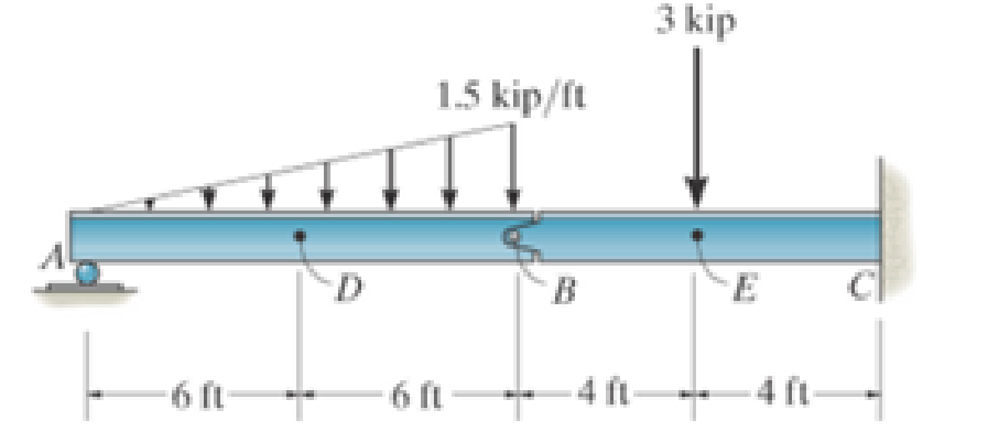
Prob. 7-25
Expert Solution & Answer
Want to see the full answer?
Check out a sample textbook solution
Students have asked these similar questions
The rod has a circular cross section. If it is made of an elastic perfectly plastic material, determine the shape factor for the rod.
prob 4
Please show work for practice prob 13
Chapter 7 Solutions
INTERNATIONAL EDITION---Engineering Mechanics: Statics, 14th edition (SI unit)
Ch. 7.1 - In each case, calculate the reaction at A and then...Ch. 7.1 - Determine the normal force, shear force, and...Ch. 7.1 - Determine the normal force, shear force, and...Ch. 7.1 - Determine the normal force, shear force, and...Ch. 7.1 - Determine the normal force, shear force, and...Ch. 7.1 - Determine the normal force, shear force, and...Ch. 7.1 - Assume A is pinned and B is a roller. Prob. F7-6Ch. 7.1 - Determine the shear force and moment at points C...Ch. 7.1 - Assume the support at B is a roller. Point C is...Ch. 7.1 - Determine the internal normal force, shear force,...
Ch. 7.1 - Determine the internal normal force, shear force,...Ch. 7.1 - If a force of 20 lb is applied to the handles,...Ch. 7.1 - Determine the distance a as a fraction of the...Ch. 7.1 - Determine the internal shear force and moment...Ch. 7.1 - Determine the internal shear force and moment...Ch. 7.1 - Take P = 8 kN. Prob. 7-9Ch. 7.1 - Determine the largest vertical load P the frame...Ch. 7.1 - Determine the internal normal force, shear force,...Ch. 7.1 - Determine the distance a between the bearings in...Ch. 7.1 - Point D is located just to the left of the 5-kip...Ch. 7.1 - The shaft is supported by a journal bearing at A...Ch. 7.1 - Determine the internal normal force, shear force,...Ch. 7.1 - Determine the internal normal force, shear force,...Ch. 7.1 - Determine the normal force, shear force, and...Ch. 7.1 - Determine the internal normal force, shear force,...Ch. 7.1 - Prob. 19PCh. 7.1 - Determine the internal normal force, shear force,...Ch. 7.1 - Point E is located just to the left of 800 N...Ch. 7.1 - Point D is located just to the left of the roller...Ch. 7.1 - Determine the internal normal force, shear force,...Ch. 7.1 - Determine the ratio of a/b for which the shear...Ch. 7.1 - Point E is just to the right of the 3-kip load....Ch. 7.1 - Determine the internal normal force, shear force,...Ch. 7.1 - Determine the internal normal force, shear force,...Ch. 7.1 - Point D is located just to the left of the 10-kN...Ch. 7.1 - Determine the normal force, shear force, and...Ch. 7.1 - Determine the normal force, shear force, and...Ch. 7.1 - Determine the internal normal force, shear force,...Ch. 7.1 - Determine the internal normal force, shear force,...Ch. 7.1 - Determine the internal normal force, shear force,...Ch. 7.1 - Determine the internal normal force, shear force,...Ch. 7.1 - If the suspended load has a weight of 2 kN and a...Ch. 7.1 - Determine the internal normal force, shear force,...Ch. 7.1 - Determine the internal normal force, shear force,...Ch. 7.1 - Determine the internal normal force, shear force,...Ch. 7.1 - The distributed loading W = W0 sin , measured per...Ch. 7.1 - Solve Prob. 7-39 for = 120. Probs. 739/40Ch. 7.1 - z components of force and moment at point C in the...Ch. 7.1 - Determine the x, y, z components of force and...Ch. 7.1 - Determine the x, y, z components of internal...Ch. 7.1 - Determine the x, y. z components of internal...Ch. 7.2 - Determine the shear and moment as a function of x,...Ch. 7.2 - Determine the shear and moment as a function of x,...Ch. 7.2 - Determine the shear and moment as a function of x,...Ch. 7.2 - Determine the shear and moment as a function of x,...Ch. 7.2 - Determine the shear and moment as a function of x,...Ch. 7.2 - Determine the shear and moment as a function of x,...Ch. 7.2 - Draw the shear and moment diagrams for the shaft...Ch. 7.2 - Draw the shear and moment diagrams for the beam...Ch. 7.2 - Draw the shear and moment diagrams for the beam...Ch. 7.2 - Draw the shear and moment diagrams for the...Ch. 7.2 - Draw the shear and moment diagrams of the beam (a)...Ch. 7.2 - If L = 9 m, the beam will fail when the maximum...Ch. 7.2 - Draw the shear and moment diagrams for the beam....Ch. 7.2 - Draw the shear and moment diagrams for the beam....Ch. 7.2 - Draw the shear and bending-moment diagrams for the...Ch. 7.2 - The shaft is supported by a smooth thrust bearing...Ch. 7.2 - Draw the shear and moment diagrams for the beam....Ch. 7.2 - Draw the shear and moment diagrams for the beam....Ch. 7.2 - Draw the shear and moment diagrams for the...Ch. 7.2 - Draw the shear and bending-moment diagrams for...Ch. 7.2 - Draw the shear and moment diagrams for the beam....Ch. 7.2 - The shaft is supported by a smooth thrust bearing...Ch. 7.2 - Draw the shear and moment diagrams for the beam....Ch. 7.2 - The beam will fail when the maximum internal...Ch. 7.2 - Draw the shear and moment diagrams for the beam....Ch. 7.2 - Draw the shear and moment diagrams for the beam....Ch. 7.2 - Draw the shear and moment diagrams for the beam....Ch. 7.2 - Draw the shear and moment diagrams for the beam....Ch. 7.2 - Determine the internal normal force, shear force,...Ch. 7.2 - The quarter circular rod lies in the horizontal...Ch. 7.2 - Express the internal shear and moment components...Ch. 7.3 - Draw the shear and moment diagrams for the beam....Ch. 7.3 - Draw the shear and moment diagrams for the beam....Ch. 7.3 - Draw the shear and moment diagrams for the beam....Ch. 7.3 - Draw the shear and moment diagrams for the beam....Ch. 7.3 - Draw the shear and moment diagrams for the beam....Ch. 7.3 - Draw the shear and moment diagrams for the beam....Ch. 7.3 - Draw the shear and moment diagrams for the beam....Ch. 7.3 - Draw the shear and moment diagrams for the beam....Ch. 7.3 - Draw the shear and moment diagrams for the beam....Ch. 7.3 - Draw the shear and moment diagrams for the...Ch. 7.3 - Draw the shear and moment diagrams for the beam....Ch. 7.3 - Draw the shear and moment diagrams for the beam....Ch. 7.3 - Draw the shear and moment diagrams for the beam....Ch. 7.3 - Draw the shear and moment diagrams for the beam....Ch. 7.3 - Draw the shear and moment diagrams for the beam....Ch. 7.3 - Draw the shear and moment diagrams for the shaft....Ch. 7.3 - Draw the shear and moment diagrams for the beam....Ch. 7.3 - The beam consists of three segments pin connected...Ch. 7.3 - Draw the shear and moment diagrams for the beam....Ch. 7.3 - Draw the shear and moment diagrams for the beam....Ch. 7.3 - Draw the shear and moment diagrams for the beam....Ch. 7.3 - Draw the shear and moment diagrams for the beam....Ch. 7.3 - Draw the shear and moment diagrams for the beam....Ch. 7.3 - Draw the shear and moment diagrams for the beam....Ch. 7.3 - Draw the shear and moment diagrams for the beam....Ch. 7.3 - Draw the shear and moment diagrams for the beam....Ch. 7.3 - Draw the shear and moment diagrams for the beam....Ch. 7.3 - Draw the shear and moment diagrams for the beam....Ch. 7.3 - Draw the shear and moment diagrams for the beam....Ch. 7.3 - Draw the shear and moment diagrams for the beam....Ch. 7.4 - The cable supports the three loads shown....Ch. 7.4 - The cable supports the three loads shown....Ch. 7.4 - Determine the tension in each segment of the cable...Ch. 7.4 - The cable supports the loading shown. Determine...Ch. 7.4 - The cable supports the loading shown. Determine...Ch. 7.4 - The cable supports the three loads shown....Ch. 7.4 - The cable supports the three loads shown....Ch. 7.4 - Determine the force P needed to hold the cable in...Ch. 7.4 - Determine the maximum uniform loading w, measured...Ch. 7.4 - The cable is subjected to a uniform loading of w =...Ch. 7.4 - The cable AB is subjected to a uniform loading of...Ch. 7.4 - Prob. 105PCh. 7.4 - If yB = 1.5 ft. determine the largest weight of...Ch. 7.4 - The cable supports a girder which weighs 850...Ch. 7.4 - Prob. 108PCh. 7.4 - If the pipe has a mass per unit length of 1500...Ch. 7.4 - Prob. 110PCh. 7.4 - Determine the maximum tension developed in the...Ch. 7.4 - Prob. 112PCh. 7.4 - The cable is subjected to the parabolic loading w...Ch. 7.4 - The power transmission cable weighs 10 lb/fl. If...Ch. 7.4 - The power transmission cable weighs 10 lb/ft. If h...Ch. 7.4 - The man picks up the 52-ft chain and holds it just...Ch. 7.4 - Prob. 117PCh. 7.4 - Prob. 118PCh. 7.4 - Prob. 119PCh. 7.4 - A telephone line (cable) stretches between two...Ch. 7.4 - Prob. 121PCh. 7.4 - Prob. 122PCh. 7.4 - A cable has a weight of 5 lb/ft. If it can span...Ch. 7.4 - Prob. 124PCh. 7.4 - Determine the internal normal force, shear force,...Ch. 7.4 - Determine the normal force, shear force, and...Ch. 7.4 - Draw the shear and moment diagrams for the beam....Ch. 7.4 - Draw the shear and moment diagrams for the beam....Ch. 7.4 - Draw the shear and moment diagrams for the beam....Ch. 7.4 - Prob. 6RP
Knowledge Booster


Learn more about
Need a deep-dive on the concept behind this application? Look no further. Learn more about this topic, mechanical-engineering and related others by exploring similar questions and additional content below.Similar questions
- ᴀɴ ᴀɪʀ-ꜱᴛᴀɴᴅᴀʀᴅ ʙʀᴀʏᴛᴏɴ ᴄʏᴄʟᴇ ʜᴀꜱ ᴀɪʀ ᴇɴᴛᴇʀ ᴛʜᴇ ᴄᴏᴍᴘʀᴇꜱꜱᴏʀ ᴀᴛ 25°ᴄ ᴀɴᴅ 101 ᴋᴘᴀ. ᴛʜᴇ ᴘʀᴇꜱꜱᴜʀᴇ ʀᴀᴛɪᴏ ɪꜱ 8, ᴀɴᴅ ᴛʜᴇ ᴍᴀxɪᴍᴜᴍ ᴀʟʟᴏᴡᴀʙʟᴇ ᴛᴇᴍᴘᴇʀᴀᴛᴜʀᴇ ɪɴ ᴛʜᴇ ᴄʏᴄʟᴇ ɪꜱ 1077°ᴄ. ɪꜰ ᴛʜᴇ ᴄʏᴄʟᴇ ɪꜱ ɪɴᴛᴇɴᴅᴇᴅ ᴛᴏ ᴘʀᴏᴅᴜᴄᴇ ᴛʜᴇ ᴛʜᴇᴏʀᴇᴛɪᴄᴀʟ ᴍᴀxɪᴍᴜᴍ ɴᴇᴛ ᴡᴏʀᴋ ɢɪᴠᴇɴ ᴛʜᴇ ᴛᴇᴍᴘᴇʀᴀᴛᴜʀᴇ ʟɪᴍɪᴛꜱ: ᴀ. ᴅᴇᴛᴇʀᴍɪɴᴇ ᴛʜᴇ ᴛᴇᴍᴘᴇʀᴀᴛᴜʀᴇꜱ ᴀᴛ ᴇᴀᴄʜ ᴘᴏɪɴᴛꜱ ᴀʀᴏᴜɴᴅ ᴛʜᴇ ᴄʏᴄʟᴇ ɪɴ °ᴄ. ʙ. ᴅᴇᴛᴇʀᴍɪɴᴇ ᴛʜᴇ ᴄᴏᴍᴘʀᴇꜱꜱᴏʀ ᴡᴏʀᴋ ᴘᴇʀ ᴋɪʟᴏɢʀᴀᴍ ᴏꜰ ᴀɪʀ. ᴄ. ᴅᴇᴛᴇʀᴍɪɴᴇ ᴛʜᴇ ᴛᴜʀʙɪɴᴇ ᴡᴏʀᴋ ᴘᴇʀ ᴋɪʟᴏɢʀᴀᴍ ᴏꜰ ᴀɪʀ. ᴅ. ᴅᴇᴛᴇʀᴍɪɴᴇ ᴛʜᴇ ᴄʏᴄʟᴇ ᴛʜᴇʀᴍᴀʟ ᴇꜰꜰɪᴄɪᴇɴᴄʏ ɪɴ %. ᴇ. ᴅʀᴀᴡ ᴛʜᴇ ᴘ-ᴠ ᴀɴᴅ ᴛ-ꜱ ᴅɪᴀɢʀᴀᴍꜱ ᴏꜰ ᴛʜᴇarrow_forwardDetermine whether or not it is stable for that position. R=0.75m h=1.50marrow_forwardThe rod has a circular cross section. If it is made of an elastic perfectly plastic material, determine the shape factor.arrow_forward
- draw and label the free body diagramarrow_forwardPresent the Free Body Diagramarrow_forwardᴀ ꜱᴛᴇᴇʟ ꜱʜᴀꜰᴛ ɪꜱ ꜱᴜʙᴊᴇᴄᴛᴇᴅ ᴛᴏ ᴀ ʙᴇɴᴅɪɴɢ ᴍᴏᴍᴇɴᴛ 9955 ɪɴ-ʟʙ ᴀɴᴅ ɪꜱ ꜱɪᴍᴜʟᴛᴀɴᴇᴏᴜꜱʟʏ ʟᴏᴀᴅᴇᴅ ᴡɪᴛʜ ᴀ ᴛᴏʀQᴜᴇ ᴏꜰ 29824 ɪɴ-ʟʙ. ɪꜰ ᴛʜᴇ ᴍᴀxɪᴍᴜᴍ ᴘᴇʀᴍɪꜱꜱɪʙʟᴇ ꜱʜᴇᴀʀ ꜱᴛʀᴇꜱꜱ ɪꜱ 3 ᴋꜱɪ, ᴡʜᴀᴛ ᴍɪɴɪᴍᴜᴍ ꜱʜᴀꜰᴛ ᴅɪᴀᴍᴇᴛᴇʀ ɪɴ ɪɴᴄʜᴇꜱ ɪꜱ ɴᴇᴄᴇꜱꜱᴀʀʏ? ʀᴏᴜɴᴅ ʏᴏᴜʀ ᴀɴꜱᴡᴇʀ ᴛᴏ 4 ꜱɪɢɴɪꜰɪᴄᴀɴᴛ ꜰɪɢᴜʀᴇꜱ.arrow_forward
- Solve Prob. 7.29 if =0.arrow_forwardI need to draw a free body diagram and the solution L=88marrow_forwardThe A-36 steel bar consists of two segments, one ofcircular cross section of radius r, and one of square crosssection. If the bar is subjected to the axial loading of P,determine the dimensions a of the square segment so thatthe strain energy within the square segment is the same asin the circular segment.arrow_forward
- Determine the horizontal displacement of joint B. Each A-36 steel member has a cross-sectional area of 2 in2.arrow_forwardᴀ ꜱʜᴀꜰᴛ ꜱᴛᴇᴘᴘɪɴɢ ꜰʀᴏᴍ 3" ᴛᴏ 4.5" ʜᴀꜱ ᴀ ꜰɪʟʟᴇᴛ ʀᴀᴅɪᴜꜱ ᴏꜰ 0.375". ᴄᴏᴍᴘᴜᴛᴇ ᴛʜᴇ ᴍᴀxɪᴍᴜᴍ ʙᴇɴᴅɪɴɢ ꜱᴛʀᴇꜱꜱ, ɪɴ ᴘꜱɪ, ɪꜰ ɪᴛ ɪꜱ ᴜɴᴅᴇʀ ᴀ ʙᴇɴᴅɪɴɢ ᴍᴏᴍᴇɴᴛ ᴏꜰ 19291 ʟʙ-ɪɴ. ʀᴏᴜɴᴅ ʏᴏᴜʀ ᴀɴꜱᴡᴇʀ ᴛᴏ 4 ꜱɪɢɴɪꜰɪᴄᴀɴᴛ ꜰɪɢᴜʀᴇꜱ.arrow_forwardBar ABC has a rectangular cross section of 300 mm by 100 mm. The attached rod DB has a diameter of 20 mm. If both members are made of A-36 steel, determine the slope at A due to the loading. Consider only the effect of bending in ABC and axial force in DB.arrow_forward
arrow_back_ios
SEE MORE QUESTIONS
arrow_forward_ios
Recommended textbooks for you
 International Edition---engineering Mechanics: St...Mechanical EngineeringISBN:9781305501607Author:Andrew Pytel And Jaan KiusalaasPublisher:CENGAGE L
International Edition---engineering Mechanics: St...
Mechanical Engineering
ISBN:9781305501607
Author:Andrew Pytel And Jaan Kiusalaas
Publisher:CENGAGE L
moment of inertia; Author: NCERT OFFICIAL;https://www.youtube.com/watch?v=A4KhJYrt4-s;License: Standard YouTube License, CC-BY