
Concept explainers
Videos
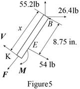
For the frame of Prob. 7.17, determine the magnitude and location of the maximum bending moment in member BC.
The bending moment of the couple exerted at the point
Answer to Problem 7.18P
The magnitude of the bending moment of couple exerted at the point
Explanation of Solution
Sketch the free body diagram for the pipe as shown in the Figure 1.
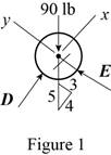
Write the equation of the axial force exerted at the axial point of the pipe from x direction.
Here, the pipe is supported by a small frame on the member is
Write the equation of the axial force exerted at the point on the pipe from y direction.
Here, the force exerted on the pipe at y direction in equilibrium condition is
Sketch the free body diagram for the frame as shown in the Figure 2.
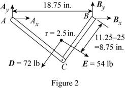
Write the equation of the moment of couple formed in the bending moment of the frame at the point
Here, the force exerted on the member of the pipe at point
Write the equation of the axial force exerted at the point on the pipe from y direction (Refer fig 2).
Here, the force exerted on the member of the pipe on frame at the point
Write the equation of the axial force exerted at the axial point of the pipe from x direction (Refer fig 2).
Sketch the free body diagram for the member of the frame from the point
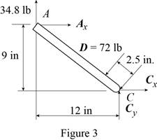
Write the equation of the moment of couple formed in the bending moment supported at the point
Here, the distance of the frame
Sketch the free body diagram for the member of the frame from the portion
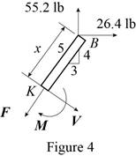
Write the equation of the moment of couple formed in the bending moment supported at the point
Sketch the free body diagram for the member of the frame from the portion
Write the equation of the moment of couple formed in the bending moment supported at the point
Conclusion:
Substitute
Substitute
Substitute
Substitute
Substitute
Substitute
Substitute
Substitute
Substitute
Substitute
Therefore, the magnitude of the bending moment of couple exerted at the point
Want to see more full solutions like this?
Chapter 7 Solutions
Connect 1 Semester Access Card for Vector Mechanics for Engineers: Statics and Dynamics


- Problem F1 Consider the frame shown. Members BE and ABCD are pinned at a 90 -degree angle. What is the magnitude and direction of the internal moment at point C?arrow_forwardCalculate the moment of the 90-N force about point o for the condition 0 = 15°, Also, determine the value of 0 for which the moment about 0 is (b)zero and (c ) a maximum., from the following answers which of them is correct: F = 90 N 800 mm 600 mm %3D 217), (c) 0 = 126.9 (or 307) %3D a) Mo =33.5 N.m CCW, (b) 0 = 36.9 (or 227), (c) 0 = 126.9 (or 317) %3D %3D 257), (c) 0 = 126.9 (or 347) %3D a) Mo =33.5 N.m CCW, (b) 0 = 36.9 (or 237), (c) 0 = 126.9 (or 327) %D а) Мо %333.5 N.m CCW, (b) ө - 36.9 (or 247), (c) 0 = 126.9 (or 337)arrow_forwardActivity 3. From a bar subjected by an axial force P, Draw the components of P acting on the inclined plane.arrow_forward
- Determine the: (A) reaction forces at both ends when the distributed load uniform and has a magnitude of 5 kN/m. (B) internal forces and moment at A for the uniformly distributed loading.arrow_forwardTwo live loads of 7 KN and 9 KN separated 5 m apart, are to cross a simple beam. Also, a uniform live load of 6 KN/m, 6 m long, is expected to cross the same beam. The simple supports are marked A and B and a point C is located 4 m from A. Determine: (a) the maximum moment at C due to the two concentrated live loads if the length of the beam is (a.1) 8.4 m; (a.2) 10 m. (b) The maximum moment at C due to the uniform live load if the length of the beam is (b.1) 8.4 m; (b.2) 10 m. (c) The maximum moment in the beam due to the combined effects of the two concentrated live loads and the uniform live loads if the length of the beam is (c.1) 8.4 m; (c.2) 10 m. part (c), I am asking for the ABSOLUTE maximum moment in the beam due to the combined effects of the two live loads and the uniform live load. Please be guided and informed accordingly. Good luck!arrow_forwardEx.3.2 (Eng'g Mech by Meriam) For the given jib crane shown, draw the FBD of the beam AB. The beam AB is a standard 0.5m l-beam witha mass of 95 kg per meter of length. The forces ON the beam AB are the: (1) tension exerted by the cable at B, 0.25 m 25° B 0.5 m (2) the applied pull (3) the reaction of the pin 1.5 m -0.12 m at A and 10 kN (4) its own weight 5 marrow_forward
- Solve Prob. 4.75 when θ = 30° and P = 150 N.arrow_forward6.70 A uniform cable weighing 15 N/m is suspended from points A and B. The force in the cable at B is known to be 500 N. Using the result of Prob. 6.69, calculate (a) the force in the cable at A; and (b) the span L. B 8 m 4 m Fig. P6.70arrow_forwardThe wheels of a wagon can be approximated as the combination of a thin outer hoop, of radius r, = 0.262 m and mass 5.08 kg, and two thin crossed rods of mass 7.37 kg each. A farmer would like to replace his wheels with uniform disks ta = 0.0462 m thick, made out of a material with a density of 7830 kg per cubic meter. If the new wheel is to have the same %3D moment of inertia about its center as the old wheel about its center, what should the radius of the disk be? ra = TOOLS X10arrow_forward
- Replace the loading system acts on beam shown in Fig. (3) by an equivalent system consists (Single Force & Couple at point A). Fig. (1) 40 N 30 N Fig. (3) 200 N-m 50 Narrow_forward3.1 A uniform horizontal beam has a length of 8 m and mass of 500 kg. The beam rests on two supports overhanging one by a distance x while the other is at the extreme right-hand end. The loading is 5 tonnes at the left-hand end, 6 tonnes at the mid-point of the beam and 7 tonnes 1 metre from the right-hand end. Determine the value of x if the reaction at the left-hand support is to be twice that at the right-hand support.- Show free-body-diagram and all your workings.arrow_forwardThe uniform 10 kg rod AB is supported by a ball and socket joint at A and by the cord CG that is attached to the midpoint G of the rod. Knowing that the rod leans against a frictionless vertical wall at B and that the tension in the cord CG, TCG=52.1 N, determine the following, Which of the following best approximates the moment of the weight of the structure about A? Choices: (7.36i + 29.4k) N-m(7.36i + 29.4j) N-m(29.4i + 7.36k) N-m(29.4i + 7.36j) N-marrow_forward
 Elements Of ElectromagneticsMechanical EngineeringISBN:9780190698614Author:Sadiku, Matthew N. O.Publisher:Oxford University Press
 Mechanics of Materials (10th Edition)Mechanical EngineeringISBN:9780134319650Author:Russell C. HibbelerPublisher:PEARSON
 Thermodynamics: An Engineering ApproachMechanical EngineeringISBN:9781259822674Author:Yunus A. Cengel Dr., Michael A. BolesPublisher:McGraw-Hill Education
 Control Systems EngineeringMechanical EngineeringISBN:9781118170519Author:Norman S. NisePublisher:WILEY
 Mechanics of Materials (MindTap Course List)Mechanical EngineeringISBN:9781337093347Author:Barry J. Goodno, James M. GerePublisher:Cengage Learning
 Engineering Mechanics: StaticsMechanical EngineeringISBN:9781118807330Author:James L. Meriam, L. G. Kraige, J. N. BoltonPublisher:WILEY