Engineering Mechanics : Statics-Practice Problems Workbook
13th Edition
ISBN: 9780132915595
Author: HIBBELER
Publisher: PEARSON
expand_more
expand_more
format_list_bulleted
Concept explainers
Videos
Textbook Question
thumb_up100%
Chapter 7.1, Problem 9P
Take P = 8 kN.
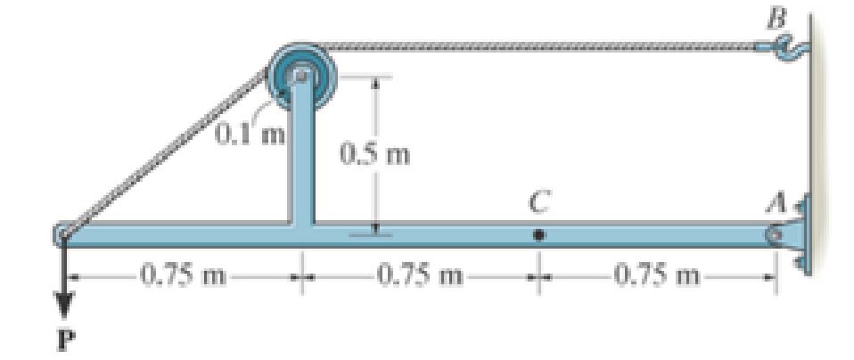
Prob. 7-9
Expert Solution & Answer
Want to see the full answer?
Check out a sample textbook solution
Students have asked these similar questions
8-12
prob 4
Please show work for practice prob 13
Chapter 7 Solutions
Engineering Mechanics : Statics-Practice Problems Workbook
Ch. 7.1 - Determine the normal force, shear force, and...Ch. 7.1 - Determine the normal force, shear force, and...Ch. 7.1 - Determine the normal force, shear force, and...Ch. 7.1 - Determine the normal force, shear force, and...Ch. 7.1 - Determine the normal force, shear force, and...Ch. 7.1 - Assume A is pinned and B is a roller. Prob. F7-6Ch. 7.1 - Assume the support at B is a roller. Point C is...Ch. 7.1 - Determine the shear force and moment at points C...Ch. 7.1 - If the suspended load has a weight of 2 kN and a...Ch. 7.1 - Prob. 4P
Ch. 7.1 - Prob. 5PCh. 7.1 - Determine the distance a as a fraction of the...Ch. 7.1 - Prob. 7PCh. 7.1 - Prob. 8PCh. 7.1 - Take P = 8 kN. Prob. 7-9Ch. 7.1 - Determine the largest vertical load P the frame...Ch. 7.1 - The shaft is supported by a journal bearing at A...Ch. 7.1 - Determine the internal normal force, shear force,...Ch. 7.1 - Prob. 13PCh. 7.1 - Prob. 14PCh. 7.1 - Prob. 15PCh. 7.1 - Prob. 16PCh. 7.1 - Prob. 17PCh. 7.1 - Point E is just to the right of the 3-kip load....Ch. 7.1 - Prob. 19PCh. 7.1 - Determine the internal normal force, shear force,...Ch. 7.1 - Prob. 21PCh. 7.1 - Prob. 22PCh. 7.1 - Prob. 23PCh. 7.1 - Determine the internal normal force, shear force,...Ch. 7.1 - Prob. 25PCh. 7.1 - Determine the ratio of a/b for which the shear...Ch. 7.1 - Prob. 27PCh. 7.1 - Prob. 28PCh. 7.1 - Determine the normal force, shear force, and...Ch. 7.1 - Determine the normal force, shear force, and...Ch. 7.1 - Prob. 31PCh. 7.1 - Prob. 32PCh. 7.1 - Prob. 33PCh. 7.1 - Prob. 34PCh. 7.1 - Prob. 35PCh. 7.1 - Prob. 36PCh. 7.1 - Prob. 37PCh. 7.1 - Prob. 38PCh. 7.1 - Prob. 39PCh. 7.1 - Prob. 40PCh. 7.1 - Determine the x, y, z components of force and...Ch. 7.1 - z components of force and moment at point C in the...Ch. 7.1 - Prob. 43PCh. 7.1 - Prob. 44PCh. 7.2 - Determine the shear and moment as a function of x,...Ch. 7.2 - Determine the shear and moment as a function of x,...Ch. 7.2 - Determine the shear and moment as a function of x,...Ch. 7.2 - Determine the shear and moment as a function of x,...Ch. 7.2 - Determine the shear and moment as a function of x,...Ch. 7.2 - Determine the shear and moment as a function of x,...Ch. 7.2 - Prob. 45PCh. 7.2 - Draw the shear and moment diagrams for the beam...Ch. 7.2 - Draw the shear and moment diagrams for the beam...Ch. 7.2 - Draw the shear and moment diagrams of the beam (a)...Ch. 7.2 - If L = 9 m, the beam will fail when the maximum...Ch. 7.2 - Draw the shear and moment diagrams for the...Ch. 7.2 - Prob. 51PCh. 7.2 - Prob. 52PCh. 7.2 - Draw the shear and moment diagrams for the beam....Ch. 7.2 - Prob. 54PCh. 7.2 - Draw the shear and bending-moment diagrams for the...Ch. 7.2 - Prob. 56PCh. 7.2 - Draw the shear and bending-moment diagrams for...Ch. 7.2 - Draw the shear and moment diagrams for the...Ch. 7.2 - Prob. 59PCh. 7.2 - The shaft is supported by a smooth thrust bearing...Ch. 7.2 - Prob. 61PCh. 7.2 - Prob. 62PCh. 7.2 - Prob. 63PCh. 7.2 - Prob. 64PCh. 7.2 - Prob. 65PCh. 7.2 - Draw the shear and moment diagrams for the beam....Ch. 7.2 - Prob. 67PCh. 7.2 - Prob. 68PCh. 7.2 - Express the internal shear and moment components...Ch. 7.3 - Draw the shear and moment diagrams for the beam....Ch. 7.3 - Draw the shear and moment diagrams for the beam....Ch. 7.3 - Draw the shear and moment diagrams for the beam....Ch. 7.3 - Draw the shear and moment diagrams for the beam....Ch. 7.3 - Draw the shear and moment diagrams for the beam....Ch. 7.3 - Draw the shear and moment diagrams for the beam....Ch. 7.3 - Prob. 70PCh. 7.3 - Prob. 71PCh. 7.3 - Draw the shear and moment diagrams for the beam....Ch. 7.3 - Prob. 73PCh. 7.3 - Draw the shear and moment diagrams for the...Ch. 7.3 - Draw the shear and moment diagrams for the beam....Ch. 7.3 - Prob. 76PCh. 7.3 - Prob. 77PCh. 7.3 - Draw the shear and moment diagrams for the shaft....Ch. 7.3 - Draw the shear and moment diagrams for the beam....Ch. 7.3 - Prob. 80PCh. 7.3 - Prob. 81PCh. 7.3 - Prob. 82PCh. 7.3 - Prob. 83PCh. 7.3 - Prob. 84PCh. 7.3 - Prob. 85PCh. 7.3 - Prob. 86PCh. 7.3 - Prob. 87PCh. 7.3 - Prob. 88PCh. 7.3 - Prob. 89PCh. 7.3 - Prob. 90PCh. 7.3 - Prob. 91PCh. 7.3 - Prob. 92PCh. 7.3 - Prob. 93PCh. 7.4 - Prob. 94PCh. 7.4 - Prob. 95PCh. 7.4 - Determine the tension in each segment of the cable...Ch. 7.4 - Prob. 97PCh. 7.4 - Prob. 98PCh. 7.4 - Prob. 99PCh. 7.4 - If cylinder E has a mass of 20 kg and each cable...Ch. 7.4 - Prob. 101PCh. 7.4 - Prob. 102PCh. 7.4 - If yB = 1.5 ft. determine the largest weight of...Ch. 7.4 - The cable AB is subjected to a uniform loading of...Ch. 7.4 - Determine the maximum uniform loading w, measured...Ch. 7.4 - The cable is subjected to a uniform loading of w =...Ch. 7.4 - Prob. 107PCh. 7.4 - Prob. 108PCh. 7.4 - If the pipe has a mass per unit length of 1500...Ch. 7.4 - Prob. 110PCh. 7.4 - Prob. 111PCh. 7.4 - Prob. 112PCh. 7.4 - Prob. 113PCh. 7.4 - A telephone line (cable) stretches between two...Ch. 7.4 - Prob. 115PCh. 7.4 - Prob. 116PCh. 7.4 - Prob. 117PCh. 7.4 - A cable has a weight of 5 lb/ft. If it can span...Ch. 7.4 - Prob. 119PCh. 7.4 - The power transmission cable weighs 10 lb/fl. If...Ch. 7.4 - The power transmission cable weighs 10 lb/ft. If h...Ch. 7.4 - Prob. 122PCh. 7.4 - Prob. 123PCh. 7.4 - The man picks up the 52-ft chain and holds it just...Ch. 7.4 - Determine the internal normal force, shear force,...Ch. 7.4 - Draw the shear and moment diagrams for the beam....Ch. 7.4 - Prob. 127RPCh. 7.4 - Prob. 128RPCh. 7.4 - Prob. 129RPCh. 7.4 - Prob. 130RPCh. 7.4 - Prob. 131RPCh. 7.4 - Prob. 132RPCh. 7.4 - Draw the shear and moment diagrams for the beam....Ch. 7.4 - Determine the normal force, shear force, and...Ch. 7.4 - Draw the shear and moment diagrams for the beam....Ch. 7.4 - Prob. 137RPCh. 7.4 - Prob. 138RPCh. 7.4 - Prob. 139RP
Additional Engineering Textbook Solutions
Find more solutions based on key concepts
Comprehension Check 7-14
The power absorbed by a resistor can be given by P = I2R, where P is power in units of...
Thinking Like an Engineer: An Active Learning Approach (3rd Edition)
23.23 A highly oxidized and uneven round bar is being turned on a lathe. Would you recommend a small or a large...
Manufacturing Engineering & Technology
3.3 It is known that a vertical force of 200 lb is required to remove the nail at C from the board. As the nail...
Vector Mechanics for Engineers: Statics, 11th Edition
Compute the hydraulic radius for a circular drain pipe running half full if its inside diameter is 300 mm.
Applied Fluid Mechanics (7th Edition)
Assume the following vectors are already defined: V1=[302]V2=[214]V3=[5131]V4=[0.50.10.20.2] For each of the fo...
Thinking Like an Engineer: An Active Learning Approach (4th Edition)
What parts are included in the vehicle chassis?
Automotive Technology: Principles, Diagnosis, And Service (6th Edition) (halderman Automotive Series)
Knowledge Booster


Learn more about
Need a deep-dive on the concept behind this application? Look no further. Learn more about this topic, mechanical-engineering and related others by exploring similar questions and additional content below.Similar questions
- Solve Prob. 7.29 if =0.arrow_forwardThe rod has a circular cross section. If it is made of an elastic perfectly plastic material, determine the shape factor for the rod.arrow_forwardThe rod has a circular cross section. If it is made of an elastic perfectly plastic material, determine the shape factor.arrow_forward
- The rigid beam is supported by three 25-mm diameters A-36 steel rods. If the beam supports the force of P = 230 kN, determine the force developed in each rod. Consider the steel to be an elastic perfectly plastic material.arrow_forwardThe truss is made of three A-36 steel members, each having a cross-sectional area of 400 mm2. Determine the horizontal displacement of the roller at C when P = 8 kN.arrow_forwardBar ABC has a rectangular cross section of 300 mm by 100 mm. The attached rod DB has a diameter of 20 mm. If both members are made of A-36 steel, determine the slope at A due to the loading. Consider only the effect of bending in ABC and axial force in DB.arrow_forward
- The rigid beam is supported by three 25-mm diameter A-36 steel rods. If the beam supports the force of P=230 kN, determine the force developed in each rod. Consider the steel to be an elastic perfectly plastic material.arrow_forwardIf the 600-kN force acts through the centroid of the cross-section, determine the location y of the centroid and the average normal stress on the cross-section. Also, sketch the normal stress distribution over the cross-section.arrow_forwardDraw the free body diagram and determine all the reationarrow_forward
- The W24 * 104 A-36 steel beam is used to support the uniform distributed load and a concentrated force which is applied at its end. If the force acts at an angle with the vertical as shown, determine the horizontal and vertical displacement at A.arrow_forwardI need to draw a free body diagram and the solution L=88marrow_forwardDraw the Free Body Diagram and solve the problemarrow_forward
arrow_back_ios
SEE MORE QUESTIONS
arrow_forward_ios
Recommended textbooks for you
 International Edition---engineering Mechanics: St...Mechanical EngineeringISBN:9781305501607Author:Andrew Pytel And Jaan KiusalaasPublisher:CENGAGE L
International Edition---engineering Mechanics: St...
Mechanical Engineering
ISBN:9781305501607
Author:Andrew Pytel And Jaan Kiusalaas
Publisher:CENGAGE L
moment of inertia; Author: NCERT OFFICIAL;https://www.youtube.com/watch?v=A4KhJYrt4-s;License: Standard YouTube License, CC-BY