
EBK STATICS AND MECHANICS OF MATERIALS
5th Edition
ISBN: 8220102955295
Author: HIBBELER
Publisher: PEARSON
expand_more
expand_more
format_list_bulleted
Videos
Textbook Question
Chapter 7.2, Problem 18P
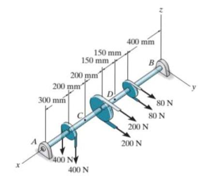
The shaft is supported at its ends by two bearings A and B and is subjected to the forces applied to the pulleys fixed to the shaft. Determine the resultant internal loadings acting on the cross section at point C. The 400-N forces act in the −z direction and the 200-N and 80-N forces act in the +y direction. The journal bearings at A and B exert only y and z components of force on the shaft.
Prob. 7-18
Expert Solution & Answer
Want to see the full answer?
Check out a sample textbook solution
Students have asked these similar questions
7-18. The shaft is supported at its ends by two bearings
A and B and is subjected to the forces applied to the pulleys
fixed to the shaft. Determine the resultant internal loadings
acting on the cross section at point C. The 400-N forces act
in the -z direction and the 200-N and 80-N forces act in the
+y direction. The journal bearings at A and B exert only y
and z components of force on the shaft.
400 mm
150 mm
150 mm
200 mm
200 mm
300 m
SON
S0N
200 N
200 N
P400 N
400 N
7-19. The shaft is supported at its ends by two bearings
A and B and is subjected to the forces applied to the pulleys
fixed to the shaft. Determine the resultant internal loadings
acting on the cross section at point D.The 400-N forces act in
the -z direction and the 200-N and 80-N forces act in the +y
direction. The journal bearings at A and B exert only y and z
components of force on the shaft.
400 mim
150 mm
150 mm
200 mm
200 mm
300 mm
80N
80N
200 N
200 N
P400 N
400 N
1-1. Determine the resultant internal normal force
acting on the cross section through point A in each column.
In (a), segment BC weighs 300 kg/m and segment CD
weighs 400 kg/m. In (b), the column has a mass of 200 kg/m.
ob daidw 8
5 kN
18 kN
В
200 mm
200 mm
6 kN
16 kN
boml
3 m
200 mm
3 m
200 mm
200 mm
200 mm
3 kNL 3 kN
4.5 kN
14.5 kN
C
1.2 m
A
1.2 m
1 m
(a)
(b)
Prob. 1-1
Chapter 7 Solutions
EBK STATICS AND MECHANICS OF MATERIALS
Ch. 7.2 - In each case, explain how to find the resultant...Ch. 7.2 - Determine the internal normal force, shear force,...Ch. 7.2 - Determine the internal normal force, shear force,...Ch. 7.2 - Determine the internal normal force, shear force,...Ch. 7.2 - Determine the internal normal force, shear force,...Ch. 7.2 - Determine the internal normal force, shear force,...Ch. 7.2 - Determine the internal normal force, shear force,...Ch. 7.2 - The shaft is supported by a smooth thrust bearing...Ch. 7.2 - Determine the resultant internal normal and shear...Ch. 7.2 - Determine the resultant internal loadings acting...
Ch. 7.2 - The shaft is supported by a smooth thrust bearing...Ch. 7.2 - Determine the resultant internal loadings acting...Ch. 7.2 - Determine the resultant internal loadings on the...Ch. 7.2 - Determine the resultant internal loadings at cross...Ch. 7.2 - Prob. 8PCh. 7.2 - The beam supports the distributed load shown....Ch. 7.2 - The boom DF of the jib crane and the column DE...Ch. 7.2 - Determine the resultant internal loadings acting...Ch. 7.2 - Determine the resultant internal loadings acting...Ch. 7.2 - The blade of the hacksaw is subjected to a...Ch. 7.2 - The blade of the hacksaw is subjected to a...Ch. 7.2 - The beam supports the triangular distributed load...Ch. 7.2 - The beam supports the distributed load shown....Ch. 7.2 - The shaft is supported at its ends by two bearings...Ch. 7.2 - The shaft is supported at its ends by two bearings...Ch. 7.2 - The hand crank that is used in a press has the...Ch. 7.2 - Determine the resultant internal loadings acting...Ch. 7.2 - Determine the resultant internal loadings acting...Ch. 7.2 - The metal stud punch is subjected to a force of...Ch. 7.2 - Determine the resultant internal loadings acting...Ch. 7.2 - Prob. 24PCh. 7.2 - Determine the resultant internal loadings acting...Ch. 7.5 - In each case, determine the largest internal shear...Ch. 7.5 - Determine the largest internal normal force in the...Ch. 7.5 - Determine the internal normal force at section A...Ch. 7.5 - The lever is held to the fixed shaft using the pin...Ch. 7.5 - Prob. 6PPCh. 7.5 - Prob. 7FPCh. 7.5 - Determine the average normal stress on the cross...Ch. 7.5 - Prob. 9FPCh. 7.5 - If the 600-kN force acts through the centroid of...Ch. 7.5 - Prob. 11FPCh. 7.5 - Prob. 12FPCh. 7.5 - The supporting wheel on a scaffold is held in...Ch. 7.5 - Determine the largest intensity w of the uniform...Ch. 7.5 - Prob. 28PCh. 7.5 - The small block has a thickness of 0.5 in. If the...Ch. 7.5 - Prob. 30PCh. 7.5 - If the block is subjected to a centrally applied...Ch. 7.5 - Prob. 32PCh. 7.5 - The board is subjected to a tensile force of 200...Ch. 7.5 - The boom has a uniform weight of 600 lb and is...Ch. 7.5 - Determine the average normal stress in each of the...Ch. 7.5 - If the average normal stress in each of the...Ch. 7.5 - Determine the maximum average shear stress in pin...Ch. 7.5 - Prob. 38PCh. 7.5 - Prob. 39PCh. 7.5 - The column is made of concrete having a density of...Ch. 7.5 - The beam is supported by two rods AB and CD that...Ch. 7.5 - The beam is supported by two rods AB and CD that...Ch. 7.5 - Prob. 43PCh. 7.5 - The railcar docklight is supported by the...Ch. 7.5 - The plastic block is subjected to an axial...Ch. 7.5 - The two steel members are joined together using a...Ch. 7.5 - The bar has a cross-sectional area of 400(106) m2....Ch. 7.5 - Prob. 48PCh. 7.5 - The two members used in the construction of an...Ch. 7.5 - Prob. 50PCh. 7.5 - Prob. 51PCh. 7.6 - Rods AC and BC are used to suspend the 200-kg...Ch. 7.6 - The pin at A has a diameter of 0.25 in. If it is...Ch. 7.6 - Prob. 15FPCh. 7.6 - Prob. 16FPCh. 7.6 - The strut is glued to the horizontal member at...Ch. 7.6 - Prob. 18FPCh. 7.6 - Prob. 19FPCh. 7.6 - Prob. 20FPCh. 7.6 - Prob. 21FPCh. 7.6 - The pin is made of a material having a failure...Ch. 7.6 - Prob. 23FPCh. 7.6 - Prob. 24FPCh. 7.6 - Prob. 52PCh. 7.6 - Prob. 53PCh. 7.6 - The connection is made using a bolt and nut and...Ch. 7.6 - The tension member is fastened together using two...Ch. 7.6 - Prob. 56PCh. 7.6 - Prob. 57PCh. 7.6 - Determine the size of square bearing plates A and...Ch. 7.6 - Determine the maximum load P that can be applied...Ch. 7.6 - Determine the required diameter of the pins at A...Ch. 7.6 - Prob. 61PCh. 7.6 - Prob. 62PCh. 7.6 - The cotter is used to hold the two rods together...Ch. 7.6 - Determine the required diameter of the pins at A...Ch. 7.6 - The steel pipe is supported on the circular base...Ch. 7.6 - Prob. 66PCh. 7.6 - The boom is supported by the winch cable that has...Ch. 7.6 - The assembly consists of three disks A, B, and C...Ch. 7.6 - Prob. 69PCh. 7.6 - The two aluminum rods AB and AC have diameters of...Ch. 7.8 - A loading causes the member to deform into the...Ch. 7.8 - Prob. 8PPCh. 7.8 - A loading causes the wires to elongate into the...Ch. 7.8 - Prob. 10PPCh. 7.8 - Prob. 11PPCh. 7.8 - Prob. 25FPCh. 7.8 - If the force P causes the rigid arm ABC to rotate...Ch. 7.8 - The rectangular plate is deformed into the shape...Ch. 7.8 - The triangular plate is deformed into the shape...Ch. 7.8 - The square plate is deformed into the shape shown...Ch. 7.8 - Prob. 71PCh. 7.8 - Prob. 72PCh. 7.8 - If the load P on the beam causes the end C to be...Ch. 7.8 - The force applied at the handle of the rigid lever...Ch. 7.8 - The rectangular plate is subjected to the...Ch. 7.8 - Prob. 76PCh. 7.8 - Prob. 77PCh. 7.8 - Prob. 78PCh. 7.8 - Prob. 79PCh. 7.8 - Prob. 80PCh. 7.8 - Determine the shear strain xy at corners D and C...Ch. 7.8 - The material distorts into the dashed position...Ch. 7.8 - Prob. 83PCh. 7.8 - Determine the shear strain xy at comers A and B if...Ch. 7.8 - Prob. 85PCh. 7.8 - Determine the average normal strain that occurs...Ch. 7.8 - The corners of the square plate are given the...Ch. 7.8 - Prob. 88PCh. 7.8 - Prob. 89PCh. 7.8 - The triangular plate is fixed at its base, and its...Ch. 7.8 - The polysulfone block is glued at its top and...Ch. 7 - The beam AB is pin supported at A and supported by...Ch. 7 - The long bolt passes through the 30-mm-thick...Ch. 7 - Determine the required thickness of member BC and...Ch. 7 - The circular punch B exerts a force of 2 kN on the...Ch. 7 - Prob. 5RPCh. 7 - Prob. 6RPCh. 7 - The square plate is deformed into the shape shown...Ch. 7 - Prob. 8RPCh. 7 - The rubber block is fixed along edge AB, and edge...
Knowledge Booster


Learn more about
Need a deep-dive on the concept behind this application? Look no further. Learn more about this topic, mechanical-engineering and related others by exploring similar questions and additional content below.Similar questions
- 1-1 Determine the resultant internal normal force acting on the cross section through point A in each column. In (a), segment BC weighs 180 lb/ft and segment CD weighs 250 lb/ft. In (b), the column has a mass of 200 kg/m. 5 kip |8 kN B 200 mm 200 mm 6 kN| 6 kN 10 ft 8 in. 3 m 8 in. 200 mm 200 mm 3 kip 3 kip 4.5 kN 14.5 kN C 4 ft A A 4 ft I m D (а) (h)arrow_forwardDetermine the x-y and n-t components of the 31-kip force Facting on the simply-supported beam. F = 31 kips L 18' B 25' 14° 43 C ∙narrow_forwardAnswer plsssssssarrow_forward
- 7-15. The force F- 400 N acts on the gear tooth. Determine the resultant internal loadings on the root of the tooth, i.e., at the centroid point A of section a-a. F- 400 N 30 5.75 mm 4 mmarrow_forwardFind the reaction at A due to the uniform loading and the applied couple. The force reaction is positive if upward, negative if downward. The moment reaction is positive if counterclockwise, negative if clockwise. 2.5 kN/m 11.1 kN-m A 2.0 m 2.0 m Answers: RA = i kN MA = i kN-marrow_forward9arrow_forward
- Determine the x-y and n-t components of the 13.0 kip force F acting on the simply supported beam. Assume a = 30 ft, b = 13 ft, 0 = 12°, and = 40° A 0 a Answers: C F b B n kips Fx = kips Fy= Fn = F₁ = Hi kips kipsarrow_forwardq1 The steel block shown in is subjected to a compressive force on all directions. Determine the change in length of Z-direction if the change in length of Y- direction is (-1.3mm). E for steel =210*10° N/mm? and u=0.28). 20cm 10cm F Scm Farrow_forwardDetermine the magnitude and direction with respect to the +x axis on the reaction at A and at C. Note that the body is supported by pin at A and a roller at C. The body's weight is negligible. 2.4 kN-m 400 40° 200 250 Dimensions in mm -300- B 3 kNarrow_forward
- 7-23. The metal stud punch is subjected to a force of 120 N on the handle. Determine the magnitude of the reactive force at the pin A and in the short link BC. Aso, determine the resultant internal loadings acting on the cross section at point D. 120 N 50 mm 100 mim 60 50 mm DV 00 mm 300 mm 200 mmarrow_forwardDraw the free-body diagram for the following problem. The rod shown.arrow_forwardThe shaft of radius c is subjected to a distributed torque t, measured as torque>length of shaft. Determine the reactions at the fixed supports A and B.arrow_forward
arrow_back_ios
SEE MORE QUESTIONS
arrow_forward_ios
Recommended textbooks for you
 Elements Of ElectromagneticsMechanical EngineeringISBN:9780190698614Author:Sadiku, Matthew N. O.Publisher:Oxford University Press
 Mechanics of Materials (10th Edition)Mechanical EngineeringISBN:9780134319650Author:Russell C. HibbelerPublisher:PEARSON
 Thermodynamics: An Engineering ApproachMechanical EngineeringISBN:9781259822674Author:Yunus A. Cengel Dr., Michael A. BolesPublisher:McGraw-Hill Education
 Control Systems EngineeringMechanical EngineeringISBN:9781118170519Author:Norman S. NisePublisher:WILEY
 Mechanics of Materials (MindTap Course List)Mechanical EngineeringISBN:9781337093347Author:Barry J. Goodno, James M. GerePublisher:Cengage Learning
 Engineering Mechanics: StaticsMechanical EngineeringISBN:9781118807330Author:James L. Meriam, L. G. Kraige, J. N. BoltonPublisher:WILEY
Elements Of Electromagnetics
Mechanical Engineering
ISBN:9780190698614
Author:Sadiku, Matthew N. O.
Publisher:Oxford University Press
Mechanics of Materials (10th Edition)
Mechanical Engineering
ISBN:9780134319650
Author:Russell C. Hibbeler
Publisher:PEARSON
Thermodynamics: An Engineering Approach
Mechanical Engineering
ISBN:9781259822674
Author:Yunus A. Cengel Dr., Michael A. Boles
Publisher:McGraw-Hill Education
Control Systems Engineering
Mechanical Engineering
ISBN:9781118170519
Author:Norman S. Nise
Publisher:WILEY
Mechanics of Materials (MindTap Course List)
Mechanical Engineering
ISBN:9781337093347
Author:Barry J. Goodno, James M. Gere
Publisher:Cengage Learning
Engineering Mechanics: Statics
Mechanical Engineering
ISBN:9781118807330
Author:James L. Meriam, L. G. Kraige, J. N. Bolton
Publisher:WILEY
BEARINGS BASICS and Bearing Life for Mechanical Design in 10 Minutes!; Author: Less Boring Lectures;https://www.youtube.com/watch?v=aU4CVZo3wgk;License: Standard Youtube License