
EBK STATICS AND MECHANICS OF MATERIALS
5th Edition
ISBN: 8220102955295
Author: HIBBELER
Publisher: PEARSON
expand_more
expand_more
format_list_bulleted
Concept explainers
Videos
Textbook Question
Chapter 7.2, Problem 9P
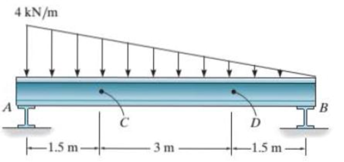
The beam supports the distributed load shown. Determine the resultant internal loadings acting on the cross section at point D. Assume the reactions at the supports A and B are vertical.
Probs. 7-8/9
Expert Solution & Answer
Want to see the full answer?
Check out a sample textbook solution
Students have asked these similar questions
explain how to find the resultant internal
loading acting on the cross section at point A. Draw all
necessary free-body diagrams, and indicate the relevant
equations of equilibrium. Do not calculate values The lettered
dimensions, angles, and loads are assumed to be known.
P7-1.
explain how to find the resultant internal
loading acting on the cross section at point A. Draw all
necessary free-body diagrams, and indicate the relevant
equations of equilibrium. Do not calculate values The lettered
dimensions, angles, and loads are assumed to be known.
P7-1.
в
The beam supports the distributed load shown. Determine the resultant internal loadings acting on the cross section at point D. Assume the reaction at the supports A and B are verticle.
Chapter 7 Solutions
EBK STATICS AND MECHANICS OF MATERIALS
Ch. 7.2 - In each case, explain how to find the resultant...Ch. 7.2 - Determine the internal normal force, shear force,...Ch. 7.2 - Determine the internal normal force, shear force,...Ch. 7.2 - Determine the internal normal force, shear force,...Ch. 7.2 - Determine the internal normal force, shear force,...Ch. 7.2 - Determine the internal normal force, shear force,...Ch. 7.2 - Determine the internal normal force, shear force,...Ch. 7.2 - The shaft is supported by a smooth thrust bearing...Ch. 7.2 - Determine the resultant internal normal and shear...Ch. 7.2 - Determine the resultant internal loadings acting...
Ch. 7.2 - The shaft is supported by a smooth thrust bearing...Ch. 7.2 - Determine the resultant internal loadings acting...Ch. 7.2 - Determine the resultant internal loadings on the...Ch. 7.2 - Determine the resultant internal loadings at cross...Ch. 7.2 - Prob. 8PCh. 7.2 - The beam supports the distributed load shown....Ch. 7.2 - The boom DF of the jib crane and the column DE...Ch. 7.2 - Determine the resultant internal loadings acting...Ch. 7.2 - Determine the resultant internal loadings acting...Ch. 7.2 - The blade of the hacksaw is subjected to a...Ch. 7.2 - The blade of the hacksaw is subjected to a...Ch. 7.2 - The beam supports the triangular distributed load...Ch. 7.2 - The beam supports the distributed load shown....Ch. 7.2 - The shaft is supported at its ends by two bearings...Ch. 7.2 - The shaft is supported at its ends by two bearings...Ch. 7.2 - The hand crank that is used in a press has the...Ch. 7.2 - Determine the resultant internal loadings acting...Ch. 7.2 - Determine the resultant internal loadings acting...Ch. 7.2 - The metal stud punch is subjected to a force of...Ch. 7.2 - Determine the resultant internal loadings acting...Ch. 7.2 - Prob. 24PCh. 7.2 - Determine the resultant internal loadings acting...Ch. 7.5 - In each case, determine the largest internal shear...Ch. 7.5 - Determine the largest internal normal force in the...Ch. 7.5 - Determine the internal normal force at section A...Ch. 7.5 - The lever is held to the fixed shaft using the pin...Ch. 7.5 - Prob. 6PPCh. 7.5 - Prob. 7FPCh. 7.5 - Determine the average normal stress on the cross...Ch. 7.5 - Prob. 9FPCh. 7.5 - If the 600-kN force acts through the centroid of...Ch. 7.5 - Prob. 11FPCh. 7.5 - Prob. 12FPCh. 7.5 - The supporting wheel on a scaffold is held in...Ch. 7.5 - Determine the largest intensity w of the uniform...Ch. 7.5 - Prob. 28PCh. 7.5 - The small block has a thickness of 0.5 in. If the...Ch. 7.5 - Prob. 30PCh. 7.5 - If the block is subjected to a centrally applied...Ch. 7.5 - Prob. 32PCh. 7.5 - The board is subjected to a tensile force of 200...Ch. 7.5 - The boom has a uniform weight of 600 lb and is...Ch. 7.5 - Determine the average normal stress in each of the...Ch. 7.5 - If the average normal stress in each of the...Ch. 7.5 - Determine the maximum average shear stress in pin...Ch. 7.5 - Prob. 38PCh. 7.5 - Prob. 39PCh. 7.5 - The column is made of concrete having a density of...Ch. 7.5 - The beam is supported by two rods AB and CD that...Ch. 7.5 - The beam is supported by two rods AB and CD that...Ch. 7.5 - Prob. 43PCh. 7.5 - The railcar docklight is supported by the...Ch. 7.5 - The plastic block is subjected to an axial...Ch. 7.5 - The two steel members are joined together using a...Ch. 7.5 - The bar has a cross-sectional area of 400(106) m2....Ch. 7.5 - Prob. 48PCh. 7.5 - The two members used in the construction of an...Ch. 7.5 - Prob. 50PCh. 7.5 - Prob. 51PCh. 7.6 - Rods AC and BC are used to suspend the 200-kg...Ch. 7.6 - The pin at A has a diameter of 0.25 in. If it is...Ch. 7.6 - Prob. 15FPCh. 7.6 - Prob. 16FPCh. 7.6 - The strut is glued to the horizontal member at...Ch. 7.6 - Prob. 18FPCh. 7.6 - Prob. 19FPCh. 7.6 - Prob. 20FPCh. 7.6 - Prob. 21FPCh. 7.6 - The pin is made of a material having a failure...Ch. 7.6 - Prob. 23FPCh. 7.6 - Prob. 24FPCh. 7.6 - Prob. 52PCh. 7.6 - Prob. 53PCh. 7.6 - The connection is made using a bolt and nut and...Ch. 7.6 - The tension member is fastened together using two...Ch. 7.6 - Prob. 56PCh. 7.6 - Prob. 57PCh. 7.6 - Determine the size of square bearing plates A and...Ch. 7.6 - Determine the maximum load P that can be applied...Ch. 7.6 - Determine the required diameter of the pins at A...Ch. 7.6 - Prob. 61PCh. 7.6 - Prob. 62PCh. 7.6 - The cotter is used to hold the two rods together...Ch. 7.6 - Determine the required diameter of the pins at A...Ch. 7.6 - The steel pipe is supported on the circular base...Ch. 7.6 - Prob. 66PCh. 7.6 - The boom is supported by the winch cable that has...Ch. 7.6 - The assembly consists of three disks A, B, and C...Ch. 7.6 - Prob. 69PCh. 7.6 - The two aluminum rods AB and AC have diameters of...Ch. 7.8 - A loading causes the member to deform into the...Ch. 7.8 - Prob. 8PPCh. 7.8 - A loading causes the wires to elongate into the...Ch. 7.8 - Prob. 10PPCh. 7.8 - Prob. 11PPCh. 7.8 - Prob. 25FPCh. 7.8 - If the force P causes the rigid arm ABC to rotate...Ch. 7.8 - The rectangular plate is deformed into the shape...Ch. 7.8 - The triangular plate is deformed into the shape...Ch. 7.8 - The square plate is deformed into the shape shown...Ch. 7.8 - Prob. 71PCh. 7.8 - Prob. 72PCh. 7.8 - If the load P on the beam causes the end C to be...Ch. 7.8 - The force applied at the handle of the rigid lever...Ch. 7.8 - The rectangular plate is subjected to the...Ch. 7.8 - Prob. 76PCh. 7.8 - Prob. 77PCh. 7.8 - Prob. 78PCh. 7.8 - Prob. 79PCh. 7.8 - Prob. 80PCh. 7.8 - Determine the shear strain xy at corners D and C...Ch. 7.8 - The material distorts into the dashed position...Ch. 7.8 - Prob. 83PCh. 7.8 - Determine the shear strain xy at comers A and B if...Ch. 7.8 - Prob. 85PCh. 7.8 - Determine the average normal strain that occurs...Ch. 7.8 - The corners of the square plate are given the...Ch. 7.8 - Prob. 88PCh. 7.8 - Prob. 89PCh. 7.8 - The triangular plate is fixed at its base, and its...Ch. 7.8 - The polysulfone block is glued at its top and...Ch. 7 - The beam AB is pin supported at A and supported by...Ch. 7 - The long bolt passes through the 30-mm-thick...Ch. 7 - Determine the required thickness of member BC and...Ch. 7 - The circular punch B exerts a force of 2 kN on the...Ch. 7 - Prob. 5RPCh. 7 - Prob. 6RPCh. 7 - The square plate is deformed into the shape shown...Ch. 7 - Prob. 8RPCh. 7 - The rubber block is fixed along edge AB, and edge...
Knowledge Booster


Learn more about
Need a deep-dive on the concept behind this application? Look no further. Learn more about this topic, mechanical-engineering and related others by exploring similar questions and additional content below.Similar questions
- Determine the support reactions for the beam on the left if w=250N/m and L=6marrow_forwardThe beam supports the distributed load shown. Determine the resultant internal loadings acting on the cross section at point C. Assume the reaction at the supports A and B are verticle.arrow_forwardThe tapered beam supports the concentrated force P at its center. Determine the absolute maximum bending stress in the beam. The reactions at the supports are vertical.arrow_forward
- 7-8. Determine the internal shear force and moment acting at point Cin the beam. 900 lb - ft 500 Ib/ft 900 Ib - ft A 61 -3 ft- Prob. 7-8arrow_forwardThe shaft is supported by a smooth thrust bearing at A and a smooth journal bearing at B. Determine the resultant internal loadings acting on the cross-section at C.arrow_forward7-11. Determine the internal normal force, shear force, and moment at points C and D of the beam. 60 lb/ft 12 ft Prob. 7-10 15 ft 40 lb/ft _B Prob. 7-11 ID -5 ft- -10 ft 690 lb 13/12arrow_forward
- 6-54. The beam is made from three boards nailed together as shown. If the moment acting on the cross section is M = 600 N - m, determine the maximum bending stress in the beam. Sketch a three-dimensional view of the stress distribution acting over the cross section. 25 mm 150 mm 20 mm 200 mm M - 600N-m 20 mmarrow_forwardexplain how to find the resultant internal loading acting on the cross section at point A. Draw all necessary free-body diagrams and indicate the relevant equations of equilibrium. Do not calculate values The lettered dimensions, angles, and loads are assumed to be known. P7-1. м в -a/2--/2-arrow_forwardDetermine the vertical reaction (A y - kN) and the reactive moment (M A - kN·m) at the support at A considering thestock values: M = 10·a + 30·b + 20·c + 200 {kN·m}, q = 20·(a + b) + 10·c + 100 {kN/m} and F = 30· (a + b+ c) + 50 {kN}. The beams AB and BC of the beam are interconnected by a smooth pin at B. Assume minimum accuracyof 6 significant figures. (a = 7; b=1 ; c=1) Ay= MA=arrow_forward
- *7-16. Determine the resultant internal loadings on the cross section through point C. Assume the reactions at the supports A and B are vertical. 6 kN 3KN/m IC 1.5 m 15 m- 0.5 m0.5 marrow_forward6-73. Determine the absolute maximum live moment in the girder bridge due to the loading shown. The load is applied directly to the girder. 2400 Ib 1800 lb 10 ft- A C B D 15 ft -- 15 ft – 15 ft - Prob. 6–73arrow_forward7-10. The beam supports the distributed load shown. Determine the resultant internal loadings acting on the cross section at point C. Assume the reactions at the supports A and B are vertical. 4 kN/m в -1.5m- -15 m-arrow_forward
arrow_back_ios
SEE MORE QUESTIONS
arrow_forward_ios
Recommended textbooks for you
 Elements Of ElectromagneticsMechanical EngineeringISBN:9780190698614Author:Sadiku, Matthew N. O.Publisher:Oxford University Press
 Mechanics of Materials (10th Edition)Mechanical EngineeringISBN:9780134319650Author:Russell C. HibbelerPublisher:PEARSON
 Thermodynamics: An Engineering ApproachMechanical EngineeringISBN:9781259822674Author:Yunus A. Cengel Dr., Michael A. BolesPublisher:McGraw-Hill Education
 Control Systems EngineeringMechanical EngineeringISBN:9781118170519Author:Norman S. NisePublisher:WILEY
 Mechanics of Materials (MindTap Course List)Mechanical EngineeringISBN:9781337093347Author:Barry J. Goodno, James M. GerePublisher:Cengage Learning
 Engineering Mechanics: StaticsMechanical EngineeringISBN:9781118807330Author:James L. Meriam, L. G. Kraige, J. N. BoltonPublisher:WILEY
Elements Of Electromagnetics
Mechanical Engineering
ISBN:9780190698614
Author:Sadiku, Matthew N. O.
Publisher:Oxford University Press
Mechanics of Materials (10th Edition)
Mechanical Engineering
ISBN:9780134319650
Author:Russell C. Hibbeler
Publisher:PEARSON
Thermodynamics: An Engineering Approach
Mechanical Engineering
ISBN:9781259822674
Author:Yunus A. Cengel Dr., Michael A. Boles
Publisher:McGraw-Hill Education
Control Systems Engineering
Mechanical Engineering
ISBN:9781118170519
Author:Norman S. Nise
Publisher:WILEY
Mechanics of Materials (MindTap Course List)
Mechanical Engineering
ISBN:9781337093347
Author:Barry J. Goodno, James M. Gere
Publisher:Cengage Learning
Engineering Mechanics: Statics
Mechanical Engineering
ISBN:9781118807330
Author:James L. Meriam, L. G. Kraige, J. N. Bolton
Publisher:WILEY
EVERYTHING on Axial Loading Normal Stress in 10 MINUTES - Mechanics of Materials; Author: Less Boring Lectures;https://www.youtube.com/watch?v=jQ-fNqZWrNg;License: Standard YouTube License, CC-BY