
MECHANICS OF MATERIAL IN SI UNITS
10th Edition
ISBN: 9781292178202
Author: HIBBELER
Publisher: PEARSON
expand_more
expand_more
format_list_bulleted
Videos
Textbook Question
Chapter 7.2, Problem 7.26P
Railroad ties must be designed to resist large shear loadings. If the tie is subjected to the 34-kip rail loadings and an assumed uniformly distributed ground reaction, determine the intensity w for equilibrium, and calculate the maximum shear stress in the tie at section a–a, which is located just to the left of the rail.
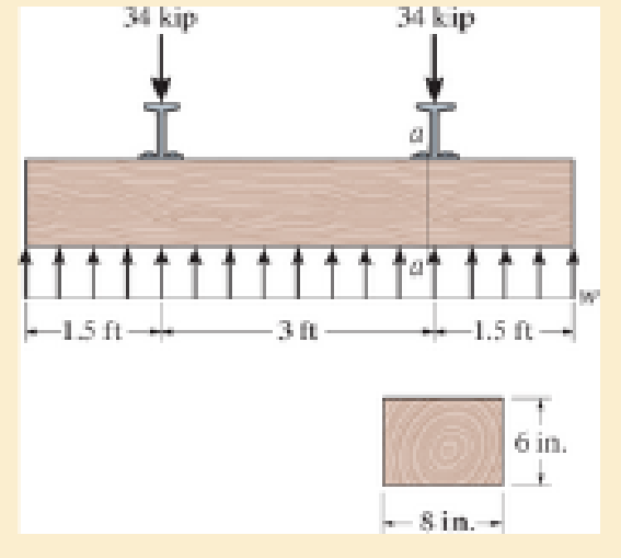
Prob. 7–26
Expert Solution & Answer
Want to see the full answer?
Check out a sample textbook solution
Students have asked these similar questions
The railcar docklight is supported by the 1/8-in.-diameter pin at A. If the lamp weighs 4.1 lb, and the extension arm AB has a weight of 0.6 lb/ft.
3 ft
-1.25 in
Part A
Determine the average shear stress in the pin needed to support the lamp. Hint:The shear force in the pin is caused by the couple moment required for equilibrium at A.
Express your answer to three significant figures and include appropriate units.
Value
Units
The railcar docklight is supported by the 1 8-in.-diameter pin at A. If the lamp weighs 4 lb, and the extension arm AB has a weight of 0.5 lb>ft, determine the average shear stress in the pin needed to support the lamp. Hint: The shear force in the pin is caused by the couple moment required for equilibrium at A.
The friction pad A is used to support the member,which is subjected to an axial force of P = 2 kN. Thepad is made from a material having a modulus ofelasticity of E = 4 MPa and Poisson’s ratio n = 0.4.If slipping does not occur, determine the normaland shear strains in the pad. The width is 50 mm.Assume that the material is linearly elastic. Also,neglect the effect of the moment acting on the pad.
Chapter 7 Solutions
MECHANICS OF MATERIAL IN SI UNITS
Ch. 7.2 - In each case, calculate the value of Q and t that...Ch. 7.2 - If the beam is subjected to a shear force of V =...Ch. 7.2 - Determine the shear stress at points A and B if...Ch. 7.2 - Determine the absolute maximum shear stress in the...Ch. 7.2 - If the beam is subjected to a shear force of V =20...Ch. 7.2 - If the beam is made from four plates and subjected...Ch. 7.2 - If the wide-flange beam is subjected to a shear of...Ch. 7.2 - If the wide-flange beam is subjected to a shear of...Ch. 7.2 - If the wide-flange beam is subjected to a shear of...Ch. 7.2 - If the beam is subjected to a shear of V = 30 kN,...
Ch. 7.2 - If the wide-flange beam is subjected to a shear of...Ch. 7.2 - The wood beam has an allowable shear stress of...Ch. 7.2 - The shaft is supported by a thrust bearing at A...Ch. 7.2 - The shaft is supported by a thrust bearing at A...Ch. 7.2 - Determine the largest shear force V that the...Ch. 7.2 - If the applied shear force V = 18 kip, determine...Ch. 7.2 - The overhang beam is subjected to the uniform...Ch. 7.2 - The beam is made from a polymer and is subjected...Ch. 7.2 - Determine the maximum shear stress in the strut if...Ch. 7.2 - Determine the maximum shear force V that the strut...Ch. 7.2 - Sketch the intensity of the shear-stress...Ch. 7.2 - Plot the shear-stress distribution over the cross...Ch. 7.2 - If the beam is subjected to a shear of V=15 kN,...Ch. 7.2 - If the wide-flange beam is subjected to a shear of...Ch. 7.2 - If the wide-flange beam is subjected to a shear of...Ch. 7.2 - Determine the length of the cantilevered beam so...Ch. 7.2 - If the beam is made from wood having an allowable...Ch. 7.2 - Determine the largest intensity w of the...Ch. 7.2 - If w=800 lb/ft, determine the absolute maximum...Ch. 7.2 - Determine the shear stress at point B on the web...Ch. 7.2 - Determine the maximum shear stress acting at...Ch. 7.2 - Railroad ties must be designed to resist large...Ch. 7.2 - The beam is slit longitudinally along both sides....Ch. 7.2 - The beam is to be cut longitudinally along both...Ch. 7.2 - The composite beam is constructed from wood and...Ch. 7.2 - The beam has a rectangular cross section and is...Ch. 7.2 - The beam in Fig.6-48f is subjected to a fully...Ch. 7.3 - The two identical boards are bolted together to...Ch. 7.3 - Two identical 20-mm-thick plates are bolted to the...Ch. 7.3 - The boards are bolted together to form the...Ch. 7.3 - The boards are bolted together to form the...Ch. 7.3 - The beam is constructed from two boards fastened...Ch. 7.3 - The beam is constructed from two boards fastened...Ch. 7.3 - The beam is constructed from three boards. If it...Ch. 7.3 - The beam is constructed from three boards....Ch. 7.3 - The double T-beam is fabricated by welding the...Ch. 7.3 - The double T-beam is fabricated by welding the...Ch. 7.3 - The beam is constructed from three boards....Ch. 7.3 - A beam is constructed from three boards bolted...Ch. 7.3 - The simply supported beam is built up from three...Ch. 7.3 - The simply supported beam is built up from three...Ch. 7.3 - The T-beam is constructed as shown. If each nail...Ch. 7.3 - The box beam is constructed from four boards that...Ch. 7.3 - The box beam is constructed from four boards that...Ch. 7.3 - The member consists of two plastic channel strips...Ch. 7.3 - The member consists of two plastic channel strips...Ch. 7.3 - The beam is made from four boards nailed together...Ch. 7.3 - The beam is made from three polystyrene strips...Ch. 7.5 - A shear force of V=300 kN is applied to the box...Ch. 7.5 - A shear force of V=450 kN is applied to the box...Ch. 7.5 - A shear force of V = 18 kN is applied to the box...Ch. 7.5 - A shear force of V = 18 kN is applied to the box...Ch. 7.5 - The aluminum strut is 10 mm thick and has the...Ch. 7.5 - The aluminum strut is 10 mm thick and has the...Ch. 7.5 - The beam is subjected to a shear force of V=50...Ch. 7.5 - The beam is subjected to a shear force of V=50...Ch. 7.5 - The H-beam is subjected to a shear of V=80 kN...Ch. 7.5 - The H-beam is subjected to a shear of V=80 kN...Ch. 7.5 - The built-up beam is formed by welding together...Ch. 7.5 - The assembly is subjected to a vertical shear of V...Ch. 7.5 - The box girder is subjected to a shear of V=15 kN....Ch. 7.5 - Determine the location e of the shear center,...Ch. 7.5 - Determine the location e of the shear center,...Ch. 7.5 - The beam supports a vertical shear of V=7 kip....Ch. 7.5 - The stiffened beam is constructed from plates...Ch. 7.5 - The pipe is subjected to a shear force of V=8 kip....Ch. 7.5 - Determine the location e of the shear center,...Ch. 7.5 - A thin plate of thickness t is bent to form the...Ch. 7.5 - Determine the location e of the shear center,...Ch. 7 - The beam is fabricated from four boards nailed...Ch. 7 - The T-beam is subjected to a shear of V = 150 kN....Ch. 7 - The member is subject to a shear force of V = 2...Ch. 7 - Determine the shear stress at points B and C on...Ch. 7 - Determine the maximum shear stress acting at...
Knowledge Booster


Learn more about
Need a deep-dive on the concept behind this application? Look no further. Learn more about this topic, mechanical-engineering and related others by exploring similar questions and additional content below.Similar questions
- determine the internal reaction components (Axial force, Shear force and Bending Moment) at Section J, and K. alpha = 20arrow_forwardThe man has a mass of 100 kg and center of mass at G. If he holds himself in the position shown, determine the maximum tensile and compressive stress developed in the curved bar at section a–a. He is supported uniformly by twobars, each having a diameter of 25 mm. Assume the floor is smooth. Use the curved-beam formula to calculate the bending stress.arrow_forwardThe assembly consists of a steel rod CB and an aluminum rod BA, each having a diameter of 15 mm. The rod is subjected to the axial loadings at A and at the coupling B. If after applying the load coupling B displaced 1.1 mm to the right, determine the change in the dimension of the cross section of steel rod CB. The unstretched length of each segment is shown in the figure. Neglect the size of the connections at B and C, and assume that they are rigid. Est = 200 GPa Vst = 0.32 %3D В A 20 kN 7 kN 3 m - 2 m·arrow_forward
- 6-70. The strut on the utility pole supports the cable having a weight of 600 lb. Determine the absolute maximum bending stress in the strut if A, B, and C are assumed to be pinned. Problem 6-70 1.5 ft C A -2 ft - 4 ft B 2 in. I 600 lb 4 in.arrow_forwardexplain how to find the resultant internal loading acting on the cross section at point A. Draw all necessary free-body diagrams and indicate the relevant equations of equilibrium. Do not calculate values The lettered dimensions, angles, and loads are assumed to be known. P7-1. м в -a/2--/2-arrow_forwardThe rows of staples AB contained in the stapler is glued together so that the maximum shear stress the glue can withstand is 12 psi. Determine the maximum force F that must be placed on the plunger in order to shear off a staple from its row and allow it to exit undeformed through the groove at C. The outer dimensions are shown in the figure below. The thickness of the staple is 0.05 in. Assume all the other parts are rigid.arrow_forward
- 7-1. The shaft is supported by a smooth thrust bearing at B and a journal bearing at C. Determine the resultant internal loadings acting on the cross section at E. 1800 N 3600 Narrow_forwardThe lever is held to the fixed shaft using the pin AB. If the couple is applied to the lever, determine the shear force in the pin between the pin and the lever.arrow_forward*7-56. The steel swivel bushing in the clevator control of an airplane is held in place using a nut and washer as shown in Fig. (a). Failure of the washer A can cause the push rod to separate as shown in Fig. (b). If the average shear stress is Tng = 145 MPa, determine the force F that must be applied to the bushing that will cause this to happen. The washer is 15 mm thick. 20 mm - (a) (b)arrow_forward
- The circular punch B exerts a force of 2 kN on the top of the plate A. Determine the average shear stress in the plate due to this loading.arrow_forwardexplain how to find the resultant internal loading acting on the cross section at point A. Draw all necessary free-body diagrams, and indicate the relevant equations of equilibrium. Do not calculate values The lettered dimensions, angles, and loads are assumed to be known. P7-1. вarrow_forward7-6. Determine the resultant internal normal and shear force in the member at (a) section a-a and (b) section b-b, each of which passes through point A. The 2000-N load is applied along the centroidal axis of the member. 30 2000 N 2000 Narrow_forward
arrow_back_ios
SEE MORE QUESTIONS
arrow_forward_ios
Recommended textbooks for you
 Elements Of ElectromagneticsMechanical EngineeringISBN:9780190698614Author:Sadiku, Matthew N. O.Publisher:Oxford University Press
 Mechanics of Materials (10th Edition)Mechanical EngineeringISBN:9780134319650Author:Russell C. HibbelerPublisher:PEARSON
 Thermodynamics: An Engineering ApproachMechanical EngineeringISBN:9781259822674Author:Yunus A. Cengel Dr., Michael A. BolesPublisher:McGraw-Hill Education
 Control Systems EngineeringMechanical EngineeringISBN:9781118170519Author:Norman S. NisePublisher:WILEY
 Mechanics of Materials (MindTap Course List)Mechanical EngineeringISBN:9781337093347Author:Barry J. Goodno, James M. GerePublisher:Cengage Learning
 Engineering Mechanics: StaticsMechanical EngineeringISBN:9781118807330Author:James L. Meriam, L. G. Kraige, J. N. BoltonPublisher:WILEY
Elements Of Electromagnetics
Mechanical Engineering
ISBN:9780190698614
Author:Sadiku, Matthew N. O.
Publisher:Oxford University Press
Mechanics of Materials (10th Edition)
Mechanical Engineering
ISBN:9780134319650
Author:Russell C. Hibbeler
Publisher:PEARSON
Thermodynamics: An Engineering Approach
Mechanical Engineering
ISBN:9781259822674
Author:Yunus A. Cengel Dr., Michael A. Boles
Publisher:McGraw-Hill Education
Control Systems Engineering
Mechanical Engineering
ISBN:9781118170519
Author:Norman S. Nise
Publisher:WILEY
Mechanics of Materials (MindTap Course List)
Mechanical Engineering
ISBN:9781337093347
Author:Barry J. Goodno, James M. Gere
Publisher:Cengage Learning
Engineering Mechanics: Statics
Mechanical Engineering
ISBN:9781118807330
Author:James L. Meriam, L. G. Kraige, J. N. Bolton
Publisher:WILEY
An Introduction to Stress and Strain; Author: The Efficient Engineer;https://www.youtube.com/watch?v=aQf6Q8t1FQE;License: Standard YouTube License, CC-BY