
MECHANICS OF MATERIAL IN SI UNITS
10th Edition
ISBN: 9781292178202
Author: HIBBELER
Publisher: PEARSON
expand_more
expand_more
format_list_bulleted
Videos
Textbook Question
Chapter 7.3, Problem 7.46P
The member consists of two plastic channel strips 0.5 in. thick, glued together at A and B. If the glue can support an allowable shear stress of τallow = 600 psi, determine the maximum intensity W0 of the triangular distributed loading that can be applied to the member based on the strength of the glue.
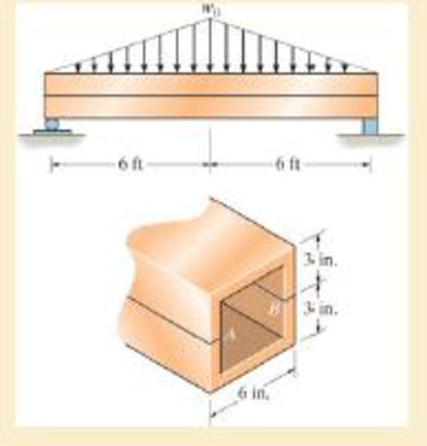
Prob. 7–46
Expert Solution & Answer
Want to see the full answer?
Check out a sample textbook solution
Students have asked these similar questions
The member consists of two plastic channel strips 0.5 in. thick, glued together at A and B. If the distributed load has a maximum intensity of w0 = 3 kip>ft, determine the maximum shear stress resisted by the glue.
8. If the allowable shear stress for each of the 10-mm-diameter steel pins at A, B, and C is
Ellow = 90 MPa, and the allowable normal stress for the 13-mm-diameter rod is Glow =
150 MPa, determine the largest intensity w of the uniform distributed load that can be
suspended from the beam.
1.2 m
B
0.9 g
Probs. 1-87/88
The strut is glued to the horizontal member at surface AB. If the strut has a thickness of 25 mm and the glue can withstand an average shear stress of 600 kPa, determine the maximum force P that can be applied to the strut.
Chapter 7 Solutions
MECHANICS OF MATERIAL IN SI UNITS
Ch. 7.2 - In each case, calculate the value of Q and t that...Ch. 7.2 - If the beam is subjected to a shear force of V =...Ch. 7.2 - Determine the shear stress at points A and B if...Ch. 7.2 - Determine the absolute maximum shear stress in the...Ch. 7.2 - If the beam is subjected to a shear force of V =20...Ch. 7.2 - If the beam is made from four plates and subjected...Ch. 7.2 - If the wide-flange beam is subjected to a shear of...Ch. 7.2 - If the wide-flange beam is subjected to a shear of...Ch. 7.2 - If the wide-flange beam is subjected to a shear of...Ch. 7.2 - If the beam is subjected to a shear of V = 30 kN,...
Ch. 7.2 - If the wide-flange beam is subjected to a shear of...Ch. 7.2 - The wood beam has an allowable shear stress of...Ch. 7.2 - The shaft is supported by a thrust bearing at A...Ch. 7.2 - The shaft is supported by a thrust bearing at A...Ch. 7.2 - Determine the largest shear force V that the...Ch. 7.2 - If the applied shear force V = 18 kip, determine...Ch. 7.2 - The overhang beam is subjected to the uniform...Ch. 7.2 - The beam is made from a polymer and is subjected...Ch. 7.2 - Determine the maximum shear stress in the strut if...Ch. 7.2 - Determine the maximum shear force V that the strut...Ch. 7.2 - Sketch the intensity of the shear-stress...Ch. 7.2 - Plot the shear-stress distribution over the cross...Ch. 7.2 - If the beam is subjected to a shear of V=15 kN,...Ch. 7.2 - If the wide-flange beam is subjected to a shear of...Ch. 7.2 - If the wide-flange beam is subjected to a shear of...Ch. 7.2 - Determine the length of the cantilevered beam so...Ch. 7.2 - If the beam is made from wood having an allowable...Ch. 7.2 - Determine the largest intensity w of the...Ch. 7.2 - If w=800 lb/ft, determine the absolute maximum...Ch. 7.2 - Determine the shear stress at point B on the web...Ch. 7.2 - Determine the maximum shear stress acting at...Ch. 7.2 - Railroad ties must be designed to resist large...Ch. 7.2 - The beam is slit longitudinally along both sides....Ch. 7.2 - The beam is to be cut longitudinally along both...Ch. 7.2 - The composite beam is constructed from wood and...Ch. 7.2 - The beam has a rectangular cross section and is...Ch. 7.2 - The beam in Fig.6-48f is subjected to a fully...Ch. 7.3 - The two identical boards are bolted together to...Ch. 7.3 - Two identical 20-mm-thick plates are bolted to the...Ch. 7.3 - The boards are bolted together to form the...Ch. 7.3 - The boards are bolted together to form the...Ch. 7.3 - The beam is constructed from two boards fastened...Ch. 7.3 - The beam is constructed from two boards fastened...Ch. 7.3 - The beam is constructed from three boards. If it...Ch. 7.3 - The beam is constructed from three boards....Ch. 7.3 - The double T-beam is fabricated by welding the...Ch. 7.3 - The double T-beam is fabricated by welding the...Ch. 7.3 - The beam is constructed from three boards....Ch. 7.3 - A beam is constructed from three boards bolted...Ch. 7.3 - The simply supported beam is built up from three...Ch. 7.3 - The simply supported beam is built up from three...Ch. 7.3 - The T-beam is constructed as shown. If each nail...Ch. 7.3 - The box beam is constructed from four boards that...Ch. 7.3 - The box beam is constructed from four boards that...Ch. 7.3 - The member consists of two plastic channel strips...Ch. 7.3 - The member consists of two plastic channel strips...Ch. 7.3 - The beam is made from four boards nailed together...Ch. 7.3 - The beam is made from three polystyrene strips...Ch. 7.5 - A shear force of V=300 kN is applied to the box...Ch. 7.5 - A shear force of V=450 kN is applied to the box...Ch. 7.5 - A shear force of V = 18 kN is applied to the box...Ch. 7.5 - A shear force of V = 18 kN is applied to the box...Ch. 7.5 - The aluminum strut is 10 mm thick and has the...Ch. 7.5 - The aluminum strut is 10 mm thick and has the...Ch. 7.5 - The beam is subjected to a shear force of V=50...Ch. 7.5 - The beam is subjected to a shear force of V=50...Ch. 7.5 - The H-beam is subjected to a shear of V=80 kN...Ch. 7.5 - The H-beam is subjected to a shear of V=80 kN...Ch. 7.5 - The built-up beam is formed by welding together...Ch. 7.5 - The assembly is subjected to a vertical shear of V...Ch. 7.5 - The box girder is subjected to a shear of V=15 kN....Ch. 7.5 - Determine the location e of the shear center,...Ch. 7.5 - Determine the location e of the shear center,...Ch. 7.5 - The beam supports a vertical shear of V=7 kip....Ch. 7.5 - The stiffened beam is constructed from plates...Ch. 7.5 - The pipe is subjected to a shear force of V=8 kip....Ch. 7.5 - Determine the location e of the shear center,...Ch. 7.5 - A thin plate of thickness t is bent to form the...Ch. 7.5 - Determine the location e of the shear center,...Ch. 7 - The beam is fabricated from four boards nailed...Ch. 7 - The T-beam is subjected to a shear of V = 150 kN....Ch. 7 - The member is subject to a shear force of V = 2...Ch. 7 - Determine the shear stress at points B and C on...Ch. 7 - Determine the maximum shear stress acting at...
Knowledge Booster


Learn more about
Need a deep-dive on the concept behind this application? Look no further. Learn more about this topic, mechanical-engineering and related others by exploring similar questions and additional content below.Similar questions
- The rigid beam is supported at its ends by two A-36 steel tie rods. The rods have diameters dAB = 0.5 in. and dCD = 0.3 in. If the allowable stress for the steel is sallow = 16.2 ksi, determine the largest intensity of the distributed load w and its length x on the beam so that the beam remains in the horizontal position when it is loaded.arrow_forwardIf the load has a weight of 600 lb, determine the maximum normal stress on the cross section of the supporting member at section a–a. Also, plot the normalstress distribution over the cross section.arrow_forwardDetermine the maximum shear force V that the strut can support if the allowable shear stress for the material is tallow = 40 MPa.arrow_forward
- The pin is used to connect the three links together. Due to wear, the load is distributed over the top and bottom of the pin as shown on the free-body diagram. If the diameter of the pin is 0.40 in., determine the maximum bending stress on the cross-sectional area at the center section a–a. For the solution it is first necessary to determine the load intensities w1 and w2.arrow_forwardThe 10-mm-diameter steel bolt is surrounded by a bronze sleeve. The outer diameter of this sleeve is 20 mm, and its inner diameter is 10 mm. If the bolt is subjected to a compressive force of P = 20 kN, determine the average normal stress in the steel and the bronze. Est = 200 GPa, Ebr = 100 GPa.arrow_forwardF7-7. Two klentical 20-mm thick plates are bollad to the top and bottom lange to form the buili-up heam. II the beam is subjected toa shear force of V = 300 KN, determine the allowable maximum spacing s of the boits to the nearest mm. Each bolt has a shcar strength of 30 RN. F7-9. The boards are boltod together to form the bull-up heam. Ir the beam is suhjactad to a shear force of V = 15 kip. determine the allowahle maximum spacing of the bolts le the nearst in. Each bolt has a shear strength of 6 kip. I in 05 in. 200 mm 3 in. 10 m 300 mm 10 mm 20 mm 7-9 FL7arrow_forward
- The screw of the clamp exerts a compressive force of 500 lb on the wood blocks. Determine the maximum normal stress along section a–a. The cross section is rectangular, 0.75 in. by 0.50 in.arrow_forwardThe beam is constructed from three plastic strips. If the glue can support a shear stress of tallow = 8 kPa, determine the largest magnitude of the loads P that the beam can support.arrow_forwardThe simply supported beam is built up from three boards by nailing them together as A, В shown. Determine the L1 L2 maximum allowable bf spacing s of the nails to support that load, if each nail can resist a tf tw shear force of V kN. hw tf P=17KN V=2kN L1=3.1m L2=2.5m bf=120mm tf=20mm hw=270mm tw=15mmarrow_forward
- F7-2 P7-3 Determine the absolute maximum shear stress developed in the beam. 3kip 61h. F-3arrow_forwardThe three suspender bars are made of steel and have equal cross-sectional areas of 450 mm?. Determine the average normal stress in each bar if the rigid beam is subjected to the loading shown. A В C 80 kN 2 m 50 kN D E -1 m- +1m- 1m-1 m-|arrow_forwardDetermine the shear stress (in Mpa) in the 23.5-mm-diameter pin at A that support the beam if P = 28.36 kN, a = 2.25 m, and b = 6.56 m.arrow_forward
arrow_back_ios
SEE MORE QUESTIONS
arrow_forward_ios
Recommended textbooks for you
 Elements Of ElectromagneticsMechanical EngineeringISBN:9780190698614Author:Sadiku, Matthew N. O.Publisher:Oxford University Press
 Mechanics of Materials (10th Edition)Mechanical EngineeringISBN:9780134319650Author:Russell C. HibbelerPublisher:PEARSON
 Thermodynamics: An Engineering ApproachMechanical EngineeringISBN:9781259822674Author:Yunus A. Cengel Dr., Michael A. BolesPublisher:McGraw-Hill Education
 Control Systems EngineeringMechanical EngineeringISBN:9781118170519Author:Norman S. NisePublisher:WILEY
 Mechanics of Materials (MindTap Course List)Mechanical EngineeringISBN:9781337093347Author:Barry J. Goodno, James M. GerePublisher:Cengage Learning
 Engineering Mechanics: StaticsMechanical EngineeringISBN:9781118807330Author:James L. Meriam, L. G. Kraige, J. N. BoltonPublisher:WILEY
Elements Of Electromagnetics
Mechanical Engineering
ISBN:9780190698614
Author:Sadiku, Matthew N. O.
Publisher:Oxford University Press
Mechanics of Materials (10th Edition)
Mechanical Engineering
ISBN:9780134319650
Author:Russell C. Hibbeler
Publisher:PEARSON
Thermodynamics: An Engineering Approach
Mechanical Engineering
ISBN:9781259822674
Author:Yunus A. Cengel Dr., Michael A. Boles
Publisher:McGraw-Hill Education
Control Systems Engineering
Mechanical Engineering
ISBN:9781118170519
Author:Norman S. Nise
Publisher:WILEY
Mechanics of Materials (MindTap Course List)
Mechanical Engineering
ISBN:9781337093347
Author:Barry J. Goodno, James M. Gere
Publisher:Cengage Learning
Engineering Mechanics: Statics
Mechanical Engineering
ISBN:9781118807330
Author:James L. Meriam, L. G. Kraige, J. N. Bolton
Publisher:WILEY
Differences between Temporary Joining and Permanent Joining.; Author: Academic Gain Tutorials;https://www.youtube.com/watch?v=PTr8QZhgXyg;License: Standard Youtube License