
Concept explainers
Videos
7.35 and 7.36 For the beam and loading shown, (a) draw the shear and bending-moment diagrams, (b) determine the maximum absolute values of the shear and bending moment.
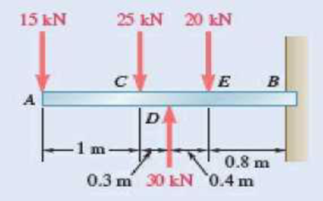
Fig. P7.35
(a)
The shear and bending-moment diagrams.
Answer to Problem 7.35P
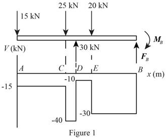
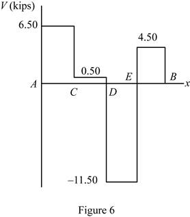
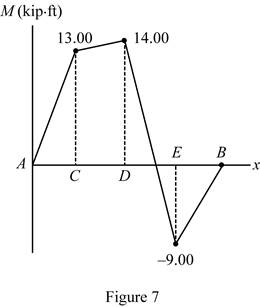
The shear diagram is drawn in figure 6 and bending momentum is drawn in figure 7.
Explanation of Solution
Refer Figure 1.
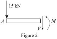
Refer Figure 2.
Write an expression to calculate the net counter clockwise moment at point C along AC.
Here,
Write an expression to calculate the net vertical force along AC.
Here,
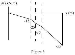
Refer Figure 3.
Write an expression to calculate the net counter clockwise moment at point D along CD.
Here,
Write an expression to calculate the net vertical force along CD.
Refer Figure 4.
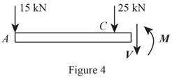
Write an expression to calculate the net counter clockwise moment at point E along DE.
Here,
Write an expression to calculate the net vertical force along EB.
Refer Figure 5.
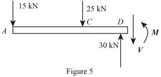
Write an expression to calculate the net counter clockwise moment at point B along EB.
Here,
Write an expression to calculate the net vertical force along EB.
Conclusion:
Refer Figure 2 and equation (II). Calculate the net vertical force.
Here,
Rearrange the equation to calculate
Refer Figure 2 and equation (I). Calculate the net counter clockwise moment at point C.
Here,
Rearrange the equation to calculate
Refer Figure 3 and equation (IV). Calculate the net vertical force.
Rearrange the equation to calculate
Refer Figure 3 and equation (III). Calculate the net counter clockwise moment at point D.
Rearrange the equation to calculate
Refer Figure 4 and equation (VI). Calculate the net vertical force.
Rearrange the equation to calculate
Refer Figure 4 and equation (V). Calculate the net counter clockwise moment at point E.
Rearrange the equation to calculate
Refer Figure 5 and equation (VIII). Calculate the net vertical force.
Rearrange the equation to calculate
Refer Figure 5 and equation (VII). Calculate the net counter clockwise moment at point E.
Rearrange the equation to calculate
Thus, draw the shear diagram.
Thus, draw the bending-moment.
(b)
The maximum absolute value of the shear and bending moment.
Answer to Problem 7.35P
The maximum absolute value of the shear force is
Explanation of Solution
Determine the maximum absolute shear from diagram 2. The maximum absolute value of bending moment is at maximum shear force.
Conclusion:
Refer figure 6. Determine the maximum absolute value of shear force.
Here,
Refer figure 7. Determine the maximum value of the bending moment at position B.
Here,
Thus, the maximum absolute value of the shear force is
Want to see more full solutions like this?
Chapter 7 Solutions
Vector Mechanics for Engineers: Statics


- Problem 03: Draw the shear and bending-moment diagrams for the beam and loading shown, and determine the maximum absolute value (a) of the shear, (b) of the bending moment.arrow_forwardDraw the shear and bending-moment diagrams for the beam and loading shown, and determine the maximum absolute value (a) of the shear, (b) of the bending momentarrow_forwardKnowing the vertical reaction at the roller support at C of the beam shown is 12.5 kN upward, determine the requested algebraic expressions for shear and moment (in terms of the variable x), using the proper sign conventions established for drawing the shear and bending moment diagrams. (a) The shear and moment equations (in terms of the variable x) for the left region of the beam between points A and B, using the F.B.D. of the left-side of your considered cut section (b) The shear and moment equations (in terms of the variable x) for the right region of the beam between points B and C using the F.B.D. of the right-side of your considered cut section.please show all steps and FBD.arrow_forward
- Two small channel sections DF and EH have been welded to the uniform beam AB of weight W = 3 kN to form the rigid structural member shown. This member is being lifted by two cables attached at D and E . Knowing that 0= 30° and neglecting the weight of the channel sections, (a) draw the shear and bending-moment diagrams for beam AB, (b) determine the maximum absolute values of the shear and bending moment in the beam.arrow_forwardDraw the shear and bending-moment diagrams for the beam and loading shown, and determine the maximum absolute value (a) of the shear, (b) of the bendingarrow_forwardFor the beam and loading shown, determine the absolute values of the shear and bending moment at 2.5 m to the left of point B.arrow_forward
- A 12-m simply supported overhang beam is supported at x = 0 and x = 10m. The overhanging portion is from x = 10m to x = 12m (the overhang portion is 2m). Two equal wheel loads of 20kN each, separated by 2m roll as a unit across the 12-m span. Determine the maximum shear developed in the span.arrow_forwardKnowing that W = 12 kN, draw the shear and bending-moment diagrams for beam AB and determine the maximum normal stress due to bending.arrow_forwardKnowing that P= 480 N,Q=320N determine (a) the distance a for which the absolute value of the bending moment in the beam is as small as possible, (b) the corresponding maximum normal stress due to bending.arrow_forward
- Determine (a) the equations of the shear and bending-moment curves for the beam and loading shown, (b) the maximum absolute value of the bending moment in the beamarrow_forwardFor the beam and loading shown, determine the maximum absolute values of the shear and bending momentarrow_forwardDetermine (a) the equations of the shear and bending moment curves for the beam and loading shown, (b) the maximum absolute value of the bending moment in the beam.arrow_forward
 Elements Of ElectromagneticsMechanical EngineeringISBN:9780190698614Author:Sadiku, Matthew N. O.Publisher:Oxford University Press
 Mechanics of Materials (10th Edition)Mechanical EngineeringISBN:9780134319650Author:Russell C. HibbelerPublisher:PEARSON
 Thermodynamics: An Engineering ApproachMechanical EngineeringISBN:9781259822674Author:Yunus A. Cengel Dr., Michael A. BolesPublisher:McGraw-Hill Education
 Control Systems EngineeringMechanical EngineeringISBN:9781118170519Author:Norman S. NisePublisher:WILEY
 Mechanics of Materials (MindTap Course List)Mechanical EngineeringISBN:9781337093347Author:Barry J. Goodno, James M. GerePublisher:Cengage Learning
 Engineering Mechanics: StaticsMechanical EngineeringISBN:9781118807330Author:James L. Meriam, L. G. Kraige, J. N. BoltonPublisher:WILEY