
Concept explainers
Videos
(a)
The distance a from the ends of the beam to the points where the cables should be attached if the maximum absolute value of the bending moment in the beam AB is the smallest.
(a)
Answer to Problem 7.61P
The distance a from the ends of the beam to the points where the cables should be attached if the maximum absolute value of the bending moment in the beam AB is the smallest is
Explanation of Solution
Refer Figure 1.
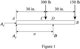
Write an expression to calculate the counter clockwise moment at point A.
Here,
Write an expression to calculate the counter clockwise moment at point A.
Here,
Write an expression to calculate the counter clockwise moment at point A.
Here,
Conclusion:
Refer Figure 1:
Calculate the moment about point A.
Here,
Rearrange the equation to calculate the D.
Substitute
Refer Figure 2.

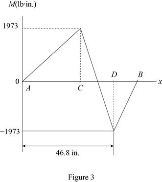
Calculate the moment about point C.
Rearrange the equation to calculate the
Substitute
Refer Figure 2.
Calculate the moment about point D.
Rearrange the equation to calculate the
Substitute
The magnitude of the maximum moment is equal to the magnitude of the minimum moment.
Substitute (I) and (II) in above equation to find a.
Rearrange the equation to find a.
Thus, the distance a from the ends of the beam to the points where the cables should be attached if the maximum absolute value of the bending moment in the beam AB is the smallest is
(b)
The value of
(b)
Answer to Problem 7.61P
The value of
Explanation of Solution
Refer Figure 4.
The magnitude of the maximum moment is equal to the magnitude of the minimum moment.
Conclusion:
Substitute
Thus, the value of
Want to see more full solutions like this?
Chapter 7 Solutions
VEC MECH 180-DAT EBOOK ACCESS(STAT+DYNA)


- For the rod of Prob. 7.23, determine the magnitude and location of the maximum bending moment.(Reference to Problem 7.23):A quarter-circular rod of weight W and uniform cross section is supported as shown. Determine the bending moment at point J when 0= 30°.arrow_forward7.74 For the beam shown, draw the shear and bending-moment dia- grams, and determine the maximum absolute value of the bending moment knowing that (a) P = 7 kips, (b) P = 10 kips. 2 kips/ft 3 kips B A 8 ft + 6 ft → 6 ft → Fig. P7.74arrow_forwardA cable AB of span L and a simple beam A'B' of the same span are subjected to identical vertical loadings as shown. Show that the magnitude of the bending moment at a point C' in the beam is equal to the product T0h, where T0 is the magnitude of the horizontal component of the tension force in the cable and h is the vertical distance between point C and the chord joining the points of support A and B.arrow_forward
- Two small channel sections DF and EH have been welded to the uniform beam AB of weight W = 3 kN to form the rigid structural member shown. This member is being lifted by two cables attached at D and E . Knowing that 0= 30° and neglecting the weight of the channel sections, (a) draw the shear and bending-moment diagrams for beam AB, (b) determine the maximum absolute values of the shear and bending moment in the beam.arrow_forward0.6 m 25 kN/m 40 kN 1.8 m 40 KN C 0.6 m D PROBLEM 5.108 (a) Using singularity functions, write the equations for the shear and bending moment for the beam and loading shown. (b) Determine the maximum value of the bending moment in the beam.arrow_forwardwhere is the location of the maximum bending moment for the beam shown below, knowing that Ra=50 KN and Rb=70 KN 10 kN/m A 6 m 30 kN/m B 2.3 m O 3.2 m O 3.4 m O 4.3 m Oarrow_forward
- Knowing that P= 480 N,Q=320N determine (a) the distance a for which the absolute value of the bending moment in the beam is as small as possible, (b) the corresponding maximum normal stress due to bending.arrow_forward27. The cantilever beam shown carries a concentrated load, P = 500 N, and a uniformly distributed load, w = 200 N/m. Determine the moment, in N-m, at a section 1.25 m to the left of the free end. Use a = b = 500 mm, and c = 1 m. a. b. 150 175 a (13 P C. d. b 200 225 W сarrow_forward7.C4 Determine the equations for the shear and bending moment curves for beams 1 and 2 shown assuming that wo = 15 kN/m and L = 3 m. Plot the shear and bending moment diagrams for each beam. TTX w = wy sin L w = wo В A L Beam 1 Beam 2 Fig. P7.C4arrow_forward
- 250 mm PROBLEM 4.3 18 mm The wide-flange beam shown is made of a high-strength, low alloy steel for which o, = 450 MPa. Using a factor of safety of 3.0, determine the largest couple that can be applied to the beam when it is bent about C 360 mm M. + 10 mm the z axis. [Ans. 243.3 kNm] 18 mm Fig. P4.3 and P4.4 PROBLEM 4.4 Solve Prob, 4.3. assuming thatarrow_forwardUsing the method of Sec. 7.3, solve Prob. 7.40.(Reference to Problem 7.40):For the beam and loading shown, (a) draw the shear and bending-moment diagrams, (b) determine the maximum absolute values of the shear and bending moment.arrow_forwardKnowing that P=Q= 480 N, determine (a) the distance a for which the absolute value of the bending moment in the beam is as small as possible, (b) the corresponding maximum normal stress due to bending.arrow_forward
 Elements Of ElectromagneticsMechanical EngineeringISBN:9780190698614Author:Sadiku, Matthew N. O.Publisher:Oxford University Press
 Mechanics of Materials (10th Edition)Mechanical EngineeringISBN:9780134319650Author:Russell C. HibbelerPublisher:PEARSON
 Thermodynamics: An Engineering ApproachMechanical EngineeringISBN:9781259822674Author:Yunus A. Cengel Dr., Michael A. BolesPublisher:McGraw-Hill Education
 Control Systems EngineeringMechanical EngineeringISBN:9781118170519Author:Norman S. NisePublisher:WILEY
 Mechanics of Materials (MindTap Course List)Mechanical EngineeringISBN:9781337093347Author:Barry J. Goodno, James M. GerePublisher:Cengage Learning
 Engineering Mechanics: StaticsMechanical EngineeringISBN:9781118807330Author:James L. Meriam, L. G. Kraige, J. N. BoltonPublisher:WILEY