
Mechanics of Materials
10th Edition
ISBN: 9780134321158
Author: HIBBELER
Publisher: PEARSON
expand_more
expand_more
format_list_bulleted
Videos
Textbook Question
Chapter 7.3, Problem 7.6FP
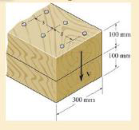
The two identical boards are bolted together to form the beam. Determine the maximum spacing s of the bolts to the nearest mm if each bolt has a shear strength of 15 kN. The beam is subjected to a shear force of V = 50 kN.
F7–6
Expert Solution & Answer

Learn your wayIncludes step-by-step video

schedule04:26
Students have asked these similar questions
Determine the maximum shear stress in the strut if it is subjected to a shear force of V = 20 kN.
The two identical boards are bolted together to form the beam. Determine the maximum spacing s of the bolts to the nearest mm if each bolt has a shear strength of 15 kN. The beam is subjected to a shear force of V = 50 kN.
Determine the maximum shear stress acting in the fiberglass beam at the section where the internal shears force is maximum. (t1=15 mm, t2=20 mm, h=150 mm, b=50mm)
Chapter 7 Solutions
Mechanics of Materials
Ch. 7.2 - In each case, calculate the value of Q and t that...Ch. 7.2 - If the beam is subjected to a shear force of V =...Ch. 7.2 - Determine the shear stress at points A and B if...Ch. 7.2 - Determine the absolute maximum shear stress in the...Ch. 7.2 - If the beam is subjected to a shear force of V =20...Ch. 7.2 - If the beam is made from four plates and subjected...Ch. 7.2 - If the wide-flange beam is subjected to a shear of...Ch. 7.2 - If the wide-flange beam is subjected to a shear of...Ch. 7.2 - If the wide-flange beam is subjected to a shear of...Ch. 7.2 - If the beam is subjected to a shear of V = 30 kN,...
Ch. 7.2 - If the wide-flange beam is subjected to a shear of...Ch. 7.2 - The wood beam has an allowable shear stress of...Ch. 7.2 - The shaft is supported by a thrust bearing at A...Ch. 7.2 - The shaft is supported by a thrust bearing at A...Ch. 7.2 - Determine the largest shear force V that the...Ch. 7.2 - If the applied shear force V = 18 kip, determine...Ch. 7.2 - The overhang beam is subjected to the uniform...Ch. 7.2 - The beam is made from a polymer and is subjected...Ch. 7.2 - Determine the maximum shear stress in the strut if...Ch. 7.2 - Determine the maximum shear force V that the strut...Ch. 7.2 - Sketch the intensity of the shear-stress...Ch. 7.2 - Plot the shear-stress distribution over the cross...Ch. 7.2 - If the beam is subjected to a shear of V=15 kN,...Ch. 7.2 - If the wide-flange beam is subjected to a shear of...Ch. 7.2 - If the wide-flange beam is subjected to a shear of...Ch. 7.2 - Determine the length of the cantilevered beam so...Ch. 7.2 - If the beam is made from wood having an allowable...Ch. 7.2 - Determine the largest intensity w of the...Ch. 7.2 - If w=800 lb/ft, determine the absolute maximum...Ch. 7.2 - Determine the shear stress at point B on the web...Ch. 7.2 - Determine the maximum shear stress acting at...Ch. 7.2 - Railroad ties must be designed to resist large...Ch. 7.2 - The beam is slit longitudinally along both sides....Ch. 7.2 - The beam is to be cut longitudinally along both...Ch. 7.2 - The composite beam is constructed from wood and...Ch. 7.2 - The beam has a rectangular cross section and is...Ch. 7.2 - The beam in Fig.6-48f is subjected to a fully...Ch. 7.3 - The two identical boards are bolted together to...Ch. 7.3 - Two identical 20-mm-thick plates are bolted to the...Ch. 7.3 - The boards are bolted together to form the...Ch. 7.3 - The boards are bolted together to form the...Ch. 7.3 - The beam is constructed from two boards fastened...Ch. 7.3 - The beam is constructed from two boards fastened...Ch. 7.3 - The beam is constructed from three boards. If it...Ch. 7.3 - The beam is constructed from three boards....Ch. 7.3 - The double T-beam is fabricated by welding the...Ch. 7.3 - The double T-beam is fabricated by welding the...Ch. 7.3 - The beam is constructed from three boards....Ch. 7.3 - A beam is constructed from three boards bolted...Ch. 7.3 - The simply supported beam is built up from three...Ch. 7.3 - The simply supported beam is built up from three...Ch. 7.3 - The T-beam is constructed as shown. If each nail...Ch. 7.3 - The box beam is constructed from four boards that...Ch. 7.3 - The box beam is constructed from four boards that...Ch. 7.3 - The member consists of two plastic channel strips...Ch. 7.3 - The member consists of two plastic channel strips...Ch. 7.3 - The beam is made from four boards nailed together...Ch. 7.3 - The beam is made from three polystyrene strips...Ch. 7.5 - A shear force of V=300 kN is applied to the box...Ch. 7.5 - A shear force of V=450 kN is applied to the box...Ch. 7.5 - A shear force of V = 18 kN is applied to the box...Ch. 7.5 - A shear force of V = 18 kN is applied to the box...Ch. 7.5 - The aluminum strut is 10 mm thick and has the...Ch. 7.5 - The aluminum strut is 10 mm thick and has the...Ch. 7.5 - The beam is subjected to a shear force of V=50...Ch. 7.5 - The beam is subjected to a shear force of V=50...Ch. 7.5 - The H-beam is subjected to a shear of V=80 kN...Ch. 7.5 - The H-beam is subjected to a shear of V=80 kN...Ch. 7.5 - The built-up beam is formed by welding together...Ch. 7.5 - The assembly is subjected to a vertical shear of V...Ch. 7.5 - The box girder is subjected to a shear of V=15 kN....Ch. 7.5 - Determine the location e of the shear center,...Ch. 7.5 - Determine the location e of the shear center,...Ch. 7.5 - The beam supports a vertical shear of V=7 kip....Ch. 7.5 - The stiffened beam is constructed from plates...Ch. 7.5 - The pipe is subjected to a shear force of V=8 kip....Ch. 7.5 - Determine the location e of the shear center,...Ch. 7.5 - A thin plate of thickness t is bent to form the...Ch. 7.5 - Determine the location e of the shear center,...Ch. 7 - The beam is fabricated from four boards nailed...Ch. 7 - The T-beam is subjected to a shear of V = 150 kN....Ch. 7 - The member is subject to a shear force of V = 2...Ch. 7 - Determine the shear stress at points B and C on...Ch. 7 - Determine the maximum shear stress acting at...
Additional Engineering Textbook Solutions
Find more solutions based on key concepts
Determine the magnitude of the resultant force acting on the plate and its direction, measured counter-clockwis...
Engineering Mechanics: Statics
13. Consider the following strange, but true, units:
1 batman = 3 kilograms [kg] 1 hogshead = 63 gallons [gal]
...
Thinking Like an Engineer: An Active Learning Approach (3rd Edition)
Determine the time of flight when it returns to its original position.
Engineering Mechanics: Dynamics (14th Edition)
4.10 Calculate the horizontal force F that should be applied to the 100 lb weight shown so that the cable AB is...
Applied Statics and Strength of Materials (6th Edition)
State if these members are in tension or compression. Probs. 6-32
INTERNATIONAL EDITION---Engineering Mechanics: Statics, 14th edition (SI unit)
The force in each member of truss and the state of members are in Tension or Compression.
Engineering Mechanics: Statics & Dynamics (14th Edition)
Knowledge Booster


Learn more about
Need a deep-dive on the concept behind this application? Look no further. Learn more about this topic, mechanical-engineering and related others by exploring similar questions and additional content below.Similar questions
- If the beam is subjected to a shear force of V = 20 kN, determine the maximum shear stress in the beam.arrow_forwardSketch the intensity of the shear-stress distribution acting over the beam’s cross-sectional area, and determine the resultant shear force acting on the segment AB. The shear force acting at the section is V = 35 kip. Show that INA = 872.49 in4.arrow_forwardIf the wide-flange beam is subjected to a shear of V = 20 kN, determine the maximum shear stress in the beam.arrow_forward
- The T-beam is subjected to a shear of V = 150 kN. Determine the amount of this force that is supported by the web B.arrow_forwardIf the wide-flange beam is subjected to a shear of V = 30 kN, determine the maximum shear stress in the beam. Set w = 300 mm.arrow_forwardThe beam is constructed from two boards. If each nail can support a shear force of 200 lb, determine the maximum spacing of the nails, s, s , and s , to the nearest 18 in. for regions AB, BC, and CD, respectivelyarrow_forward
- If the wide-flange beam is subjected to a shear of V = 30 kN, determine the shear force resisted by the web of the beam. Set w = 200 mm.arrow_forwardIf the beam is subjected to a shear of V = 30 kN, determine the web’s shear stress at A and B. Indicate the shear-stress components on a volume element located at these points. Set w = 200 mm. Show that the neutral axisis located at y = 0.2433 m from the bottom and I = 0.5382(10−3) m4.arrow_forwardThe cantilevered beam has a circular cross section. If it supports a force P at its end, determine its radius y as a function of x so that it is subjected to a constant maximum bending stress sallow throughout its length.arrow_forward
- The solid aluminum shaft has a diameter of 50 mm. Determine the absolute maximum shear stress in the shaft and sketch the shear-stress distribution along a radial line of the shaft where the shear stress is maximum. Set T1 = 2000 N # m.arrow_forwardIf the beam is subjected to a shear of V = 15 kN, determine the web’s shear stress at A and B. Indicate the shear-stress components on a volume elementlocated at these points. Set w = 125 mm. Show that the neutral axis is located at y = 0.1747 m from the bottom and INA = 0.2182(10−3) m4.arrow_forwardIf the wide-flange beam is subjected to a shear force V = 30 kN, determine the shear force resisted by the web of the beam. Consider w = 200 mmarrow_forward
arrow_back_ios
SEE MORE QUESTIONS
arrow_forward_ios
Recommended textbooks for you
 Elements Of ElectromagneticsMechanical EngineeringISBN:9780190698614Author:Sadiku, Matthew N. O.Publisher:Oxford University Press
 Mechanics of Materials (10th Edition)Mechanical EngineeringISBN:9780134319650Author:Russell C. HibbelerPublisher:PEARSON
 Thermodynamics: An Engineering ApproachMechanical EngineeringISBN:9781259822674Author:Yunus A. Cengel Dr., Michael A. BolesPublisher:McGraw-Hill Education
 Control Systems EngineeringMechanical EngineeringISBN:9781118170519Author:Norman S. NisePublisher:WILEY
 Mechanics of Materials (MindTap Course List)Mechanical EngineeringISBN:9781337093347Author:Barry J. Goodno, James M. GerePublisher:Cengage Learning
 Engineering Mechanics: StaticsMechanical EngineeringISBN:9781118807330Author:James L. Meriam, L. G. Kraige, J. N. BoltonPublisher:WILEY
Elements Of Electromagnetics
Mechanical Engineering
ISBN:9780190698614
Author:Sadiku, Matthew N. O.
Publisher:Oxford University Press
Mechanics of Materials (10th Edition)
Mechanical Engineering
ISBN:9780134319650
Author:Russell C. Hibbeler
Publisher:PEARSON
Thermodynamics: An Engineering Approach
Mechanical Engineering
ISBN:9781259822674
Author:Yunus A. Cengel Dr., Michael A. Boles
Publisher:McGraw-Hill Education
Control Systems Engineering
Mechanical Engineering
ISBN:9781118170519
Author:Norman S. Nise
Publisher:WILEY
Mechanics of Materials (MindTap Course List)
Mechanical Engineering
ISBN:9781337093347
Author:Barry J. Goodno, James M. Gere
Publisher:Cengage Learning
Engineering Mechanics: Statics
Mechanical Engineering
ISBN:9781118807330
Author:James L. Meriam, L. G. Kraige, J. N. Bolton
Publisher:WILEY
Mechanics of Materials Lecture: Beam Design; Author: UWMC Engineering;https://www.youtube.com/watch?v=-wVs5pvQPm4;License: Standard Youtube License