
Mechanics of Materials
10th Edition
ISBN: 9780134321158
Author: HIBBELER
Publisher: PEARSON
expand_more
expand_more
format_list_bulleted
Concept explainers
Videos
Textbook Question
Chapter 7.2, Problem 7.24P
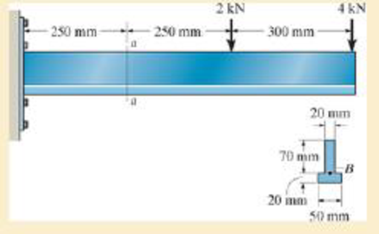
Determine the shear stress at point B on the web of the cantilevered strut at section a–a.
Probs. 7–24/25
Expert Solution & Answer
Want to see the full answer?
Check out a sample textbook solution
Students have asked these similar questions
The board is subjected to a tensile force of 200 lb. Determine the average normal and average shear stress in the wood fibers, which are oriented along plane a–a at 20° with the axis of the board.
The shaft is hollow from A to B and solid from B to C. Determine the maximum shear stress in the shaft. The shaft has an outer diameter of 80 mm, and the thickness of the wall of the hollow segment is 10 mm.
1–1. The shaft is supported by a smooth thrust bearing at B and a journal bearing at C. Determine the resultant internal loadings acting on the cross section at E.
Problem 1–1
Chapter 7 Solutions
Mechanics of Materials
Ch. 7.2 - In each case, calculate the value of Q and t that...Ch. 7.2 - If the beam is subjected to a shear force of V =...Ch. 7.2 - Determine the shear stress at points A and B if...Ch. 7.2 - Determine the absolute maximum shear stress in the...Ch. 7.2 - If the beam is subjected to a shear force of V =20...Ch. 7.2 - If the beam is made from four plates and subjected...Ch. 7.2 - If the wide-flange beam is subjected to a shear of...Ch. 7.2 - If the wide-flange beam is subjected to a shear of...Ch. 7.2 - If the wide-flange beam is subjected to a shear of...Ch. 7.2 - If the beam is subjected to a shear of V = 30 kN,...
Ch. 7.2 - If the wide-flange beam is subjected to a shear of...Ch. 7.2 - The wood beam has an allowable shear stress of...Ch. 7.2 - The shaft is supported by a thrust bearing at A...Ch. 7.2 - The shaft is supported by a thrust bearing at A...Ch. 7.2 - Determine the largest shear force V that the...Ch. 7.2 - If the applied shear force V = 18 kip, determine...Ch. 7.2 - The overhang beam is subjected to the uniform...Ch. 7.2 - The beam is made from a polymer and is subjected...Ch. 7.2 - Determine the maximum shear stress in the strut if...Ch. 7.2 - Determine the maximum shear force V that the strut...Ch. 7.2 - Sketch the intensity of the shear-stress...Ch. 7.2 - Plot the shear-stress distribution over the cross...Ch. 7.2 - If the beam is subjected to a shear of V=15 kN,...Ch. 7.2 - If the wide-flange beam is subjected to a shear of...Ch. 7.2 - If the wide-flange beam is subjected to a shear of...Ch. 7.2 - Determine the length of the cantilevered beam so...Ch. 7.2 - If the beam is made from wood having an allowable...Ch. 7.2 - Determine the largest intensity w of the...Ch. 7.2 - If w=800 lb/ft, determine the absolute maximum...Ch. 7.2 - Determine the shear stress at point B on the web...Ch. 7.2 - Determine the maximum shear stress acting at...Ch. 7.2 - Railroad ties must be designed to resist large...Ch. 7.2 - The beam is slit longitudinally along both sides....Ch. 7.2 - The beam is to be cut longitudinally along both...Ch. 7.2 - The composite beam is constructed from wood and...Ch. 7.2 - The beam has a rectangular cross section and is...Ch. 7.2 - The beam in Fig.6-48f is subjected to a fully...Ch. 7.3 - The two identical boards are bolted together to...Ch. 7.3 - Two identical 20-mm-thick plates are bolted to the...Ch. 7.3 - The boards are bolted together to form the...Ch. 7.3 - The boards are bolted together to form the...Ch. 7.3 - The beam is constructed from two boards fastened...Ch. 7.3 - The beam is constructed from two boards fastened...Ch. 7.3 - The beam is constructed from three boards. If it...Ch. 7.3 - The beam is constructed from three boards....Ch. 7.3 - The double T-beam is fabricated by welding the...Ch. 7.3 - The double T-beam is fabricated by welding the...Ch. 7.3 - The beam is constructed from three boards....Ch. 7.3 - A beam is constructed from three boards bolted...Ch. 7.3 - The simply supported beam is built up from three...Ch. 7.3 - The simply supported beam is built up from three...Ch. 7.3 - The T-beam is constructed as shown. If each nail...Ch. 7.3 - The box beam is constructed from four boards that...Ch. 7.3 - The box beam is constructed from four boards that...Ch. 7.3 - The member consists of two plastic channel strips...Ch. 7.3 - The member consists of two plastic channel strips...Ch. 7.3 - The beam is made from four boards nailed together...Ch. 7.3 - The beam is made from three polystyrene strips...Ch. 7.5 - A shear force of V=300 kN is applied to the box...Ch. 7.5 - A shear force of V=450 kN is applied to the box...Ch. 7.5 - A shear force of V = 18 kN is applied to the box...Ch. 7.5 - A shear force of V = 18 kN is applied to the box...Ch. 7.5 - The aluminum strut is 10 mm thick and has the...Ch. 7.5 - The aluminum strut is 10 mm thick and has the...Ch. 7.5 - The beam is subjected to a shear force of V=50...Ch. 7.5 - The beam is subjected to a shear force of V=50...Ch. 7.5 - The H-beam is subjected to a shear of V=80 kN...Ch. 7.5 - The H-beam is subjected to a shear of V=80 kN...Ch. 7.5 - The built-up beam is formed by welding together...Ch. 7.5 - The assembly is subjected to a vertical shear of V...Ch. 7.5 - The box girder is subjected to a shear of V=15 kN....Ch. 7.5 - Determine the location e of the shear center,...Ch. 7.5 - Determine the location e of the shear center,...Ch. 7.5 - The beam supports a vertical shear of V=7 kip....Ch. 7.5 - The stiffened beam is constructed from plates...Ch. 7.5 - The pipe is subjected to a shear force of V=8 kip....Ch. 7.5 - Determine the location e of the shear center,...Ch. 7.5 - A thin plate of thickness t is bent to form the...Ch. 7.5 - Determine the location e of the shear center,...Ch. 7 - The beam is fabricated from four boards nailed...Ch. 7 - The T-beam is subjected to a shear of V = 150 kN....Ch. 7 - The member is subject to a shear force of V = 2...Ch. 7 - Determine the shear stress at points B and C on...Ch. 7 - Determine the maximum shear stress acting at...
Additional Engineering Textbook Solutions
Find more solutions based on key concepts
What parts are included in the vehicle chassis?
Automotive Technology: Principles, Diagnosis, And Service (6th Edition) (halderman Automotive Series)
Find the change in length of side AB.
Mechanics of Materials, 7th Edition
Convert the following quantities from English to SI units: a. 98 Btu/(hr-ft-F) b. 0.24 Btu/(lbm-F) C. 0.04 Ibm/...
Heating Ventilating and Air Conditioning: Analysis and Design
A biological fluid moves at a flow rate of m=0.02kg/s through a coiled, thin-walled, 5-mm-diameter tube submerg...
Fundamentals of Heat and Mass Transfer
Three rigid bodies, 2,3, and 4, are connected by four springs as shown in the figure. A horizontal force of 1,0...
Introduction To Finite Element Analysis And Design
Describe the structural changes that take place when a plain-carbon eutectoid steel is slowly cooled from the a...
Foundations of Materials Science and Engineering
Knowledge Booster


Learn more about
Need a deep-dive on the concept behind this application? Look no further. Learn more about this topic, mechanical-engineering and related others by exploring similar questions and additional content below.Similar questions
- Determine the shear stress at point B on the web of the cantilevered strut at section a–a.arrow_forwardDetermine the shape factor of the cross section.arrow_forwardDetermine the vertical displacement of end B of the frame. Consider only bending strain energy. The frame is made using two A-36 steel W460 * 68 wide-flange sections.arrow_forward
- Determine the average shear stress in the plate due to this loading.arrow_forwardDetermine the maximum shear stress in the strut if it is subjected to a shear force of V = 20 kN.arrow_forwardThe assembly consists of two sections of galvanized steel pipe connected together using a reducing coupling at B. The smaller pipe has an outer diameter of 0.75 in. and an inner diameter of 0.68 in., whereas the larger pipe has an outer diameter of 1 in. and an inner diameter of 0.86 in. If the pipe istightly secured to the wall at C, determine the maximum shear stress in each section of the pipe when the couple is applied to the handles of the wrench.arrow_forward
- The L2 steel blade of the band saw wraps around the pulley having a radius of 12 in. Determine the maximum normal stress in the blade. The blade has a width of 0.75 in. and a thickness of 0.0625 inarrow_forwardDetermine the maximum shear stress acting in the fiberglass beam at the section where the internal shears force is maximum. (t1=15 mm, t2=20 mm, h=150 mm, b=50mm)arrow_forwardThe screw of the clamp exerts a compressive force of 500 lb on the wood blocks. Determine the maximum normal stress along section a–a. The cross section is rectangular, 0.75 in. by 0.50 in.arrow_forward
- The solid shaft is fixed to the support at C and subjected to the torsional loadings. Determine the shear stress at points A and B on the surface, and sketch the shear stress on volume elements located at these points.arrow_forwardDetermine the stress distribution of the beam in cross section A-B when its dimensions are a = 4.0 m, b = 0.5 m, c = 124 mm, and d = 100 mm. The magnitude of the force P is 35 kN. How much are in cross section A-B normal force shear force bending moment normal stress at the top of the beam normal stress at the lower surface of the beam maximum shear stress shear stress at y = 62 mm from the lower levelarrow_forwardThe pin is used to connect the three links together. Due to wear, the load is distributed over the top and bottom of the pin as shown on the free-body diagram. If the diameter of the pin is 0.40 in., determine the maximum bending stress on the cross-sectional area at the center section a–a. For the solution it is first necessary to determine the load intensities w1 and w2.arrow_forward
arrow_back_ios
SEE MORE QUESTIONS
arrow_forward_ios
Recommended textbooks for you
 Elements Of ElectromagneticsMechanical EngineeringISBN:9780190698614Author:Sadiku, Matthew N. O.Publisher:Oxford University Press
 Mechanics of Materials (10th Edition)Mechanical EngineeringISBN:9780134319650Author:Russell C. HibbelerPublisher:PEARSON
 Thermodynamics: An Engineering ApproachMechanical EngineeringISBN:9781259822674Author:Yunus A. Cengel Dr., Michael A. BolesPublisher:McGraw-Hill Education
 Control Systems EngineeringMechanical EngineeringISBN:9781118170519Author:Norman S. NisePublisher:WILEY
 Mechanics of Materials (MindTap Course List)Mechanical EngineeringISBN:9781337093347Author:Barry J. Goodno, James M. GerePublisher:Cengage Learning
 Engineering Mechanics: StaticsMechanical EngineeringISBN:9781118807330Author:James L. Meriam, L. G. Kraige, J. N. BoltonPublisher:WILEY
Elements Of Electromagnetics
Mechanical Engineering
ISBN:9780190698614
Author:Sadiku, Matthew N. O.
Publisher:Oxford University Press
Mechanics of Materials (10th Edition)
Mechanical Engineering
ISBN:9780134319650
Author:Russell C. Hibbeler
Publisher:PEARSON
Thermodynamics: An Engineering Approach
Mechanical Engineering
ISBN:9781259822674
Author:Yunus A. Cengel Dr., Michael A. Boles
Publisher:McGraw-Hill Education
Control Systems Engineering
Mechanical Engineering
ISBN:9781118170519
Author:Norman S. Nise
Publisher:WILEY
Mechanics of Materials (MindTap Course List)
Mechanical Engineering
ISBN:9781337093347
Author:Barry J. Goodno, James M. Gere
Publisher:Cengage Learning
Engineering Mechanics: Statics
Mechanical Engineering
ISBN:9781118807330
Author:James L. Meriam, L. G. Kraige, J. N. Bolton
Publisher:WILEY
Everything About COMBINED LOADING in 10 Minutes! Mechanics of Materials; Author: Less Boring Lectures;https://www.youtube.com/watch?v=N-PlI900hSg;License: Standard youtube license