
Concept explainers
Videos
Knowing that dc = 9 ft, determine (a) the distances dB and dD (b) the reaction at E.
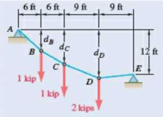
Fig. P7.99 and P7.100
(a)
The distances
Answer to Problem 7.99P
The distance
Explanation of Solution
Refer Fig P7.99.
The figure 1 below shows the free body diagram of the portion ABC.
The total moment about the point C is zero.
Refer the free body diagram and write the equation for the moment about point C.
Here
Re-write the above equation to get an expression for
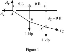
The figure 2 below shows the free body diagram of the entire cable.
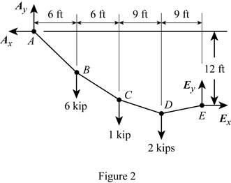
The moment about point E is zero.
Refer the free body diagram of the entire cable and write the equation of the moment about point E.
Simplify the above equation.
Since the system is in equilibrium the total vertical and horizontal components will be zero.
Refer figure 2 and write the equation for total horizontal force.
Here
Refer figure 2 and write the equation for the total vertical force.
The figure 4 below shows the free body diagram of the portion AB.
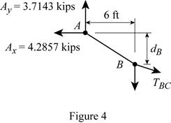
The moment about point B is zero.
Refer figure 4 and write the equation for the moment about point B.
The figure 5 below shows the free body diagram of the portion DE.
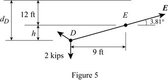
Refer figure 5 and write the formula for the distance
Here
Refer figure 5 and write the formula for distance
Conclusion:
Substitute equation (I) in equation (II).
Substitute
Substitute
Substitute
Substitute
Calculate
Substitute
The distance
(b)
The reaction at point E.
Answer to Problem 7.99P
The reaction at point E is
Explanation of Solution
Refer Fig P7.99.
The figure 1 below shows the free body diagram of the portion ABC.
The total moment about the point C is zero.
Refer the free body diagram and write the equation for the moment about point C.
Here
Re-write the above equation to get an expression for
The figure 2 below shows the free body diagram of the entire cable.
The moment about point E is zero.
Refer the free body diagram of the entire cable and write the equation of the moment about point E.
Simplify the above equation.
Since the system is in equilibrium the total vertical and horizontal components will be zero.
Refer figure 2 and write the equation for total horizontal force.
Here
Refer figure 2 and write the equation for the total vertical force.
Write the formula for the magnitude of the reaction at point E.
Here
Write the formula for the angle made by the reaction at point E with horizontal.
Here
Conclusion:
Substitute equation (I) in equation (II).
Substitute
Substitute
Substitute
Substitute
Substitute
Thus the reaction at point E is
Want to see more full solutions like this?
Chapter 7 Solutions
CE 99 STATICS-W/ACCESS (LL) >IP<


- (a) Determine the maximum allowable horizontal span for a uniform cable with a weight per unit length of w if the tension in the cable is not to exceed a given value Tm. (b) Using the result of part a , determine the maximum span of a steel wire for which w = 0.25 lb/ft and Tm = 8000 lb.arrow_forwardShow that the curve assumed by a cable that carries a distributed load w(x) is defined by the differential equation d2y/dx2 = w(x)/t0, ehere T0 is the tension at the lowest point.arrow_forwardCable ACB supports a load uniformly distributed along the horizontal as shown. The lowest point C is located 9 m to the right of A . Determine (a) the vertical distance a,(b) the length of the cable, (c) the components of the reaction at A.arrow_forward
- Each cable of the Golden Gate Bridge supports a load w = 11.1 kips/ft along the horizontal. Knowing that the span L is 4150 ft and that the sag h is 464 ft, determine (a) the maximum tension in each cable, (b) the length of each cable.arrow_forwardThe uniform 10 kg rod AB is supported by a ball and socket joint at A and by the cord CG that is attached to the midpoint G of the rod. Knowing that the rod leans against a frictionless vertical wall at B and that the tension in the cord CG, TCG=52.1 N, determine the following, Which of the following best approximates the moment of the weight of the structure about A? Choices: (7.36i + 29.4k) N-m(7.36i + 29.4j) N-m(29.4i + 7.36k) N-m(29.4i + 7.36j) N-marrow_forwardKnowing that the distance h has been selected to maximize the distance y from line BB, to the centroid of the shaded area, show that y = 2h/3.arrow_forward
- Knowing that the radius of each pulley is 200 mm and neglecting friction. determine the internal forces at point K of the frame shown.Fig. P7.18arrow_forwardA tractor with a wheelbase of y = 6 m carries 922 N of its load on the rear wheels and 606 N of its load on the front wheels. Determine the distance x so that the reaction of the beam at A is twice as great as the reaction at B.arrow_forwardThe beam in the figures below has the cross section and loading indicated therein;determine for the most requested section, knowing that the allowable normal voltage is 1400kgf/cm².a) Determine the sum of forces in X, Y and Momentumarrow_forward
- Google Lens Q2/ Knowing that the forces values given as: F1=32 N , F2=45 N , F3=60 N , *1=0.7 m , x2=0.4m , H=1.5m.a) Determine the x components of reactions at fixed support point Aarrow_forwardA counterweight D is attached to a cable that passes over a small pulley at A and is attached to a support at B . Knowing that L = 45 ft and h = 15 ft, determine (a) the length of the cable from A to B, (b) the weight per unit length of the cable. Neglect the weight of the cable from A to D.arrow_forwardThree bars, two made of aluminum and one made of steel, support a rigid block. An object of weight W is dropped vertically from a distance h above the rigid block. Both steel and aluminum bars have cross-sectional area of 50 mm2 and length of 0.5 m. The elastic moduli for the aluminum and steel are 76 GPa and 184 GPa, respectively. a) If W=1000N and h=0.1m, determine whether the three bars are still safe to perform. b) If h=0.2m, determine the maximum weight that can be dropped without causing failure to the barsarrow_forward
 Elements Of ElectromagneticsMechanical EngineeringISBN:9780190698614Author:Sadiku, Matthew N. O.Publisher:Oxford University Press
 Mechanics of Materials (10th Edition)Mechanical EngineeringISBN:9780134319650Author:Russell C. HibbelerPublisher:PEARSON
 Thermodynamics: An Engineering ApproachMechanical EngineeringISBN:9781259822674Author:Yunus A. Cengel Dr., Michael A. BolesPublisher:McGraw-Hill Education
 Control Systems EngineeringMechanical EngineeringISBN:9781118170519Author:Norman S. NisePublisher:WILEY
 Mechanics of Materials (MindTap Course List)Mechanical EngineeringISBN:9781337093347Author:Barry J. Goodno, James M. GerePublisher:Cengage Learning
 Engineering Mechanics: StaticsMechanical EngineeringISBN:9781118807330Author:James L. Meriam, L. G. Kraige, J. N. BoltonPublisher:WILEY