
Concept explainers
Videos
The compressed-air tank AB has a 250-rnm outside diameter and an 8-mm wall thickness. It is fitted with a collar by which a 40-kN force P is applied at B in the horizontal direction. Knowing that the gage pressure inside the tank is 5 MPa, determine the maximum normal stress and the maximum shearing stress at point K.
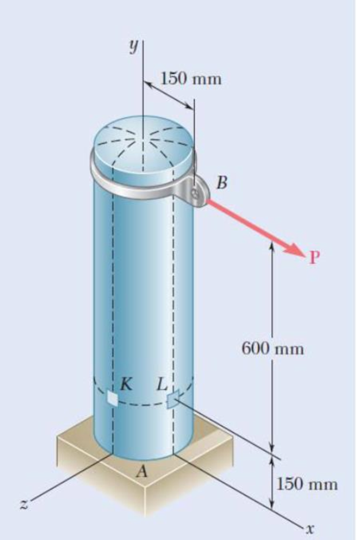
Fig. P7.124
Find the maximum normal stress and maximum shear stress at point K.
Answer to Problem 124P
The maximum normal stress and maximum shear stress at point K are
Explanation of Solution
Given information:
The outer diameter (d) of the tank is
The wall thickness (t) of the tank is
The magnitude of the load P is
The gage pressure (p) inside the tank is
Calculation:
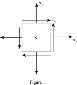
Consider an element at point K.
Show the stress acting on the point K as shown in Figure 1.
Calculate the inner radius of the vessel
Substitute
Show the expression for hoop stress acting on the tank as shown below.
Substitute
Show the expression for longitudinal stress acting on the vessel as shown below.
Substitute
Calculate the stress due to bending at point K as follows:
The point K lies in the neutral axis, then
The stress due to bending at point K,
Calculate the stress due to transverse shear as follows:
Consider the shear force acting on the tank is denoted by V. Then,
Consider the distance between the centre of the circular cross-section to the inner and outer surface of the wall are denoted by
Calculate the shear flow Q using the relation:
Substitute
Calculate the moment of inertia I of the cross-section using the relation:
Substitute
Calculate the shear stress using the relation:
Substitute
Show the total hoop stress
Calculate the radius of the Mohr circle using the relation:
Substitute
Show the expression for average stress acting on the vessel as shown below.
Substitute
Consider the principal stress are denoted by
Calculate the value of the
Substitute
Calculate the value of the
Substitute
The stress at point C is 0. Then,
Compare the value of stress
Get the maximum and minimum value of the stress as follows:
Thus, the maximum normal stress in the tank is
Calculate the maximum shear stress in the tank using the relation:
Substitute
Thus, the maximum shear stress in the tank is
Want to see more full solutions like this?
Chapter 7 Solutions
MECHANICS OF MATERIALSW/CONNECT>(LL)<>


- A torque of magnitude T=12 kN·m is applied to the end of a tank containing compressed air under a pressure of 8 MPa. Knowing that the tank has a 180-mm inner diameter and a 12-mm wall thickness, determine the maximum normal stress and the maximum in-plane shearing stress in the tank.arrow_forwardThe compressed-air tank AB has an inner diameter of 450 mm and a uniform wall thickness of 6 mm. Knowing that the gage pressure inside the tank is 1.2 MPa, determine the maximum normal stress and the maximum in-plane shearing stress at point a on the top of the tank.arrow_forwardA fabric used in air-inflated structures is subjected to a biaxial loading that results in normal stresses ox = 18 ksi and oz = 24 ksi.Knowing that the properties of the fabric can be approximated as E = 12.6 x 10 psi and v = 0.34, determine the change in length of (a) side AB, (b) side BC, (c) diagonal AC.arrow_forward
- Each of the four vertical Ilinks has an 8 x 36-mm uniform rectangular cross section and each of the four pins has a 16-mm diameter. Take P= 19 kN. 0.4 m C 0.25 m 0.2 m B. P Determine the average bearing stress at Bin member ABC, knowing that this member has a 10 x 50-mm uniform rectangular cross section. MPa. The average bearing stress at Bin member ABC is.arrow_forwardA timber beam AB of length L and rectangular cross section carries a single concentrated load P at its midpoint C. (a) Show that the ratio Tm/ m of the maximum values of the shearing and normal stresses in the beam is equal to h/2L, where h and L are, respectively, the depth and the length of the beam. (b) Determine the depth h and the width b of the beam, knowing that L = 2 m, P = 40 kN, 7m = 960 kPa, and om = 12 MPa.arrow_forwardA standard-weight steel pipe of 12-in. nominal diameter carries water under a pressure of 400 psi. (a) Knowing that the outside diameter is 12.75 in. and the wall thickness is 0.375 in., determine the maximum tensile stress in the pipe. (b) Solve part a, assuming that an extra-strong pipe is used, of 12.75-in. outside diameter and 0.5-in. wall thickness.arrow_forward
- For the truss and loading shown, determine the magnitude of the normal stress(in psi) in member CE, knowing that the cross-sectional area of that member is 3.67 in2 if P = 30505 lb, Q = 34758 lb, and y = 7.35 ft. Round off the final answer to two decimal places.arrow_forwardA steel shaft and an aluminum tube are connected to a fixed support and to a rigid disk as shown in the cross section. Knowing that the initial stresses are zero, determine the maximum torque T0 that can be applied to the disk if the allowable stresses are 120 MPa in the steel shaft and 70 MPa in the aluminum tube. Use G= 77 GPa for steel and G = 27 GPa for aluminum.arrow_forwardFor the state of stress shown, it is known that the normal and shearing stresses are directed as shown and that σx = 15.5 ksi, σy = 9 ksi, and σmin = 5 ksi. Determine the orientation of the principal planes. Determine the principal stress σmax. Determine the maximum in plane shearing stressarrow_forward
- A steel pipe of 400-mm outer diameter is fabricated from 10-mm-thick plate by welding along a helix that forms an angle of 20°with a plane perpendicular to the axis of the pipe. Knowing that the maximum allowable normal and shearing stresses in the directions respectively normal and tangential to the weld are σ = 60 MPa and τ = 36 MPa, determine the magnitude P of the largest axial force that can be applied to the pipe.arrow_forwardThe 4.5-ft concrete post is reinforced with six steel bars, each with a 118-in. diameter. Knowing that Es5 29 3 106 psi and Ec5 4.2 3 106 psi, determine the normal stresses in the steel and in the concrete when a 350-kip axial centric force P is applied to the postarrow_forwardThe aluminum rod AD is fitted with a jacket that is used to apply a hydrostatic pressure of 6000 psi to the 12-in. portion BC of the rod. Knowing that E=10.1* 106 psi and ν=0.36, determine (a) the change in the total length AD, (b) the change in diameter at the middle of the rod, determine the forces that should be applied to the ends A and D of the rod (a) if the axial strain in portion BC of the rod is to remain zero as the hydrostatic pressure is applied, (b) if the total length AD of the rod is to remain unchangedarrow_forward
 Elements Of ElectromagneticsMechanical EngineeringISBN:9780190698614Author:Sadiku, Matthew N. O.Publisher:Oxford University Press
 Mechanics of Materials (10th Edition)Mechanical EngineeringISBN:9780134319650Author:Russell C. HibbelerPublisher:PEARSON
 Thermodynamics: An Engineering ApproachMechanical EngineeringISBN:9781259822674Author:Yunus A. Cengel Dr., Michael A. BolesPublisher:McGraw-Hill Education
 Control Systems EngineeringMechanical EngineeringISBN:9781118170519Author:Norman S. NisePublisher:WILEY
 Mechanics of Materials (MindTap Course List)Mechanical EngineeringISBN:9781337093347Author:Barry J. Goodno, James M. GerePublisher:Cengage Learning
 Engineering Mechanics: StaticsMechanical EngineeringISBN:9781118807330Author:James L. Meriam, L. G. Kraige, J. N. BoltonPublisher:WILEY