For pressure-driven, steady, fully developed laminar flow of an incompressible fluid through a straight channel of length L , we can define the hydraulic resistance as R hyd = Δ p / Q , where Δ p is the pressure drop and Q is the flow rate (analogous to the electrical resistance R elec = Δ V / I , where Δ V is the electrical potential drop and I is the electric current). The following table summarizes the hydraulic resistance of channels with different cross sectional shapes [30]: Calculate the hydraulic resistance of a straight channel with the listed cross-sectional shapes using the following parameters for water flow: μ = 1 mPa_s, L = 10 mm, a = 100 μ m, b = 33 μ m, h = 100 μ m, and w = 300 μ m. Based on the calculated hydraulic resistance, which shape is the most energy efficient to pump water?
For pressure-driven, steady, fully developed laminar flow of an incompressible fluid through a straight channel of length L , we can define the hydraulic resistance as R hyd = Δ p / Q , where Δ p is the pressure drop and Q is the flow rate (analogous to the electrical resistance R elec = Δ V / I , where Δ V is the electrical potential drop and I is the electric current). The following table summarizes the hydraulic resistance of channels with different cross sectional shapes [30]: Calculate the hydraulic resistance of a straight channel with the listed cross-sectional shapes using the following parameters for water flow: μ = 1 mPa_s, L = 10 mm, a = 100 μ m, b = 33 μ m, h = 100 μ m, and w = 300 μ m. Based on the calculated hydraulic resistance, which shape is the most energy efficient to pump water?
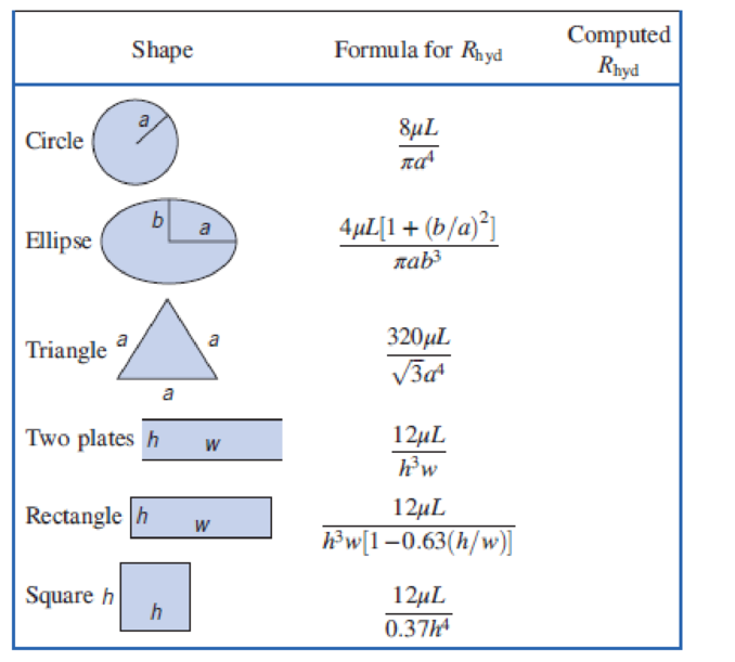
For pressure-driven, steady, fully developed laminar flow of an incompressible fluid through a straight channel of length L, we can define the hydraulic resistance as Rhyd = Δp/Q, where Δp is the pressure drop and Q is the flow rate (analogous to the electrical resistance Relec = ΔV/I, where ΔV is the electrical potential drop and I is the electric current). The following table summarizes the hydraulic resistance of channels with different cross sectional shapes [30]:
Calculate the hydraulic resistance of a straight channel with the listed cross-sectional shapes using the following parameters for water flow: μ = 1 mPa_s, L = 10 mm,a = 100 μm, b = 33 μm, h = 100μm, and w = 300 μm. Based on the calculated hydraulic resistance, which shape is the most energy efficient to pump water?
In our country, using natural resources, it is desired to generate electricity by placing a turbine between two water sources. The tangential velocity to the impeller of this turbine is calculated by the formula u = kuLaTeX: \ sqrt {2gHo} 2gHo. Here; The tangential velocity coefficient can be taken as ku = 0.46 ± 0.02, the head which represents the net energy in the turbine as H0 = 650 ± 5% m and the gravitational acceleration as 9.81 m / s2. Find the tangential velocity and the percentage error at that velocity.
PP:PE
ميكانيك نضري محاضرة 15 .pdf
crease of the flowrate by a factor of
Qu, G tan(e/2) VTe (3H, A
On C, tan(a/2) VE (HYA
= 15.6
(Ans)
H.W1:Water flows steadily through the large tanks shown in fig.
below. What is the water depth, h, ?
Page 5
Northern Technical University
Technical college of Engineering / Mosul
Engineering Mechanics (II)(second year)
FIGURE P3.58
(1)
0.03 -m diameter
(2)
(3)
0.05 - m diameter
2 m
here
(4)
1. h,=50.4 m
2. h,=15.4 m
3. h,=5.4 m
4. h,-25.4
m.
H.W:What is the manometer reading, h, for the flow shown in fig.
below?
0.37
0.08 m
diametar
0.05 m diameter
1. h=0.73 m
2. h=0.54 m
3. h=0.25 m
4. h=0.37 m
H.W3: What is flowrate through the submerged orifice shown in fig.
below, if the contraction coefficient C,=0.63 ?
(1)
3dn.
diameter
1. Q=0.351 ft'is 2. Q=0.351 m'is 3. Q=0.451 ft'/s
fe'/s.
4. Q=0.351
Page 6
The velocity distribution in a 0.02 m
diameter horizontal pipe conveying carbon
tetrachloride (specific gravity = 1.59,
absolute viscosity = 9.6 x 10⁻⁶ Pa sec) is
given by the parabolic equation:
v(r)=0.01(0.12- r?), where v(r) is the velocity
in (m/s) at a distance r in (m) from the pipe
center. What is discharge?
O a.
3.13 x-8 m3/s
O b. None of the mentioned
O c. 1.047 x 10⁸ m3/sec
O d. 4.97 x 10⁹ m3/sec
Chapter 8 Solutions
Fox And Mcdonald's Introduction To Fluid Mechanics
Thinking Like an Engineer: An Active Learning Approach (4th Edition)
Knowledge Booster
Learn more about
Need a deep-dive on the concept behind this application? Look no further. Learn more about this topic, mechanical-engineering and related others by exploring similar questions and additional content below.


 Elements Of ElectromagneticsMechanical EngineeringISBN:9780190698614Author:Sadiku, Matthew N. O.Publisher:Oxford University Press
 Mechanics of Materials (10th Edition)Mechanical EngineeringISBN:9780134319650Author:Russell C. HibbelerPublisher:PEARSON
 Thermodynamics: An Engineering ApproachMechanical EngineeringISBN:9781259822674Author:Yunus A. Cengel Dr., Michael A. BolesPublisher:McGraw-Hill Education
 Control Systems EngineeringMechanical EngineeringISBN:9781118170519Author:Norman S. NisePublisher:WILEY
 Mechanics of Materials (MindTap Course List)Mechanical EngineeringISBN:9781337093347Author:Barry J. Goodno, James M. GerePublisher:Cengage Learning
 Engineering Mechanics: StaticsMechanical EngineeringISBN:9781118807330Author:James L. Meriam, L. G. Kraige, J. N. BoltonPublisher:WILEY