
Videos
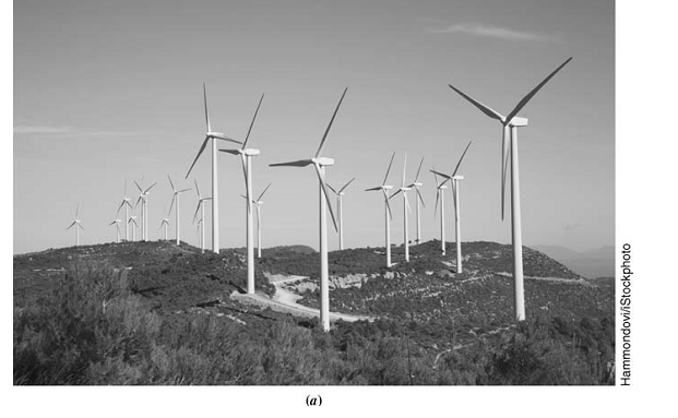
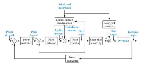
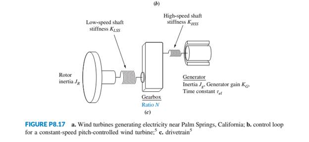
Wind turbines, such as the one shown in Figure P8.17 (a), are becoming popular as a way of generating electricity. Feedback control loops are designed to control the output power of the turbine, given an input power demand. Blade-pitch control may be used as part of the control loop for a constant-speed, pitch-controlled wind turbine, as shown in figure P8.17 (b). The drivetrain, consisting of the windmill rotor, gearbox, and electric generator (see Figure P8.17(c)), is part of the control loop. The torque created by the wind drives the rotor. The windmill rotor is connected to the generator through a gearbox.
The transfer function of the drivetrain is
where
(Anderson, 1998). Do the following for the drivetrain dynamics, making use of any computational aids at your disposal:
a. Sketch a root locus that shows the pole locations of
b. Find the value of N that yields a pair of complex poles of
Want to see the full answer?
Check out a sample textbook solution
Chapter 8 Solutions
CONTROL SYSTEMS ENGINEERING - WILEYPLUS


- 1. Give an example of open loop and closed loop system (one example each). Also state the input, control system, feedback and output parameter. Example. 1. Open Loop - Water Heater: Input - Water Temperature (Cold) System - Heating Element Output - Water Temperature (Hot) 2. Closed Loop - Air-conditioning System Input - Desired Room Temperature Control - Motor controller/Compressor/ACU Feedback - Temperature Sensing Output - Room Temperaturearrow_forwarda)is the aircraft stable about the equilibrium represented by the transfer function? b) Using proportional feedback,what is the range of acceptable gains for the closed loop systen to be stable? c) Design a feedback control system that allows the pilot to command a pitch angle with overshoot less than or equal to 4.15% and a natural frequency of greater than or equal to 0.99 rad/s d) Design a feedback control system that allows the pilot to command a pitch angle with the same overshoot and a natural frequency of one half the system in part c.arrow_forwardFor a unity negative feedback control system having an open-loop transfer function, G(s) as given below. Find out the value of "K" such that the system will be in the stable region. (K/s) (s3 + 12. 5s2 + 50. 5s + 66) G(s) =arrow_forward
- A Block diagram of a feedback control system is shown in Figure Q3. Using the Block Diagram Reduction Method, solve for the output Y(s) when:(i) Input D(s) = 0,(ii) Input R(s) = 0,(iii) Input R(s) and D(s) are both applied (i.e., R(s) ≠ 0 , D(s) ≠ 0).arrow_forwardOne of the disadvantage of negative feedback loop is lag caused because it can only be exerted after controlled variable has been disturbed. In order to minimize lag between a change in a controlled variable and the action of the effector, it is advantageous for the body to anticipate any likely change. Which one of the following physiological mechanism achieves this? Select one: a. Feedbackward control b. Feedforward control c.Positive feedback control d. All of the above e. None of the abovearrow_forwardthrottle actuator velocity v intake pipe throttle angle (aTH) slope (a) For vehicle speed control example our control task as follow: Desired (specified) behaviour: keep vehicle speed constant Manipulation: automatically adjust gas/brake pedal position Show block diagram representation clearly.arrow_forward
- As the control engineer on a project you are given the following information: a) The free body diagram representation of a mechanical system with the various values for the damper, spring and mass. The transfer function for the system is also provided. 28 N/m -x(1) 1 G(s): - f(1) s? +s+5.6 5 kg 5 N-s/m b) The step response plot for the system. Step Response 0.14 0.12 0.1 0.08 0.06 0.04 0.02 10 Time (sec) Your task is to analyse the system and to confirm that the diagram is for the system in a) i.e. calculate all time responses and compare your answers with the data in the graph. apnaduarrow_forward4(а) Describe, in your own words, the difference between a deterministic finite automa- ton and a nondeterministic automaton. 4(b) In your own words compare and contrast a Linear Bounded Automaton, a Push- down Automaton and a Turing Machine. 4(c) Design a Turing Machine that takes 2 unary numbers on the tape, where the first number is greater than the second number, and computes and writes a unary number to the tape that is the first number minus the second number.arrow_forwardQUESTION 5 Consider the system whose block diagram is shown below. D(s) R(s) + + C(s) K G(s) G(8) R(s) is the reference input or target, and D(s) is the disturbance input. Gp(t) is the plant (house, motor, car,...) transfer function, Gc(t) is the compensator transfer function, and K is the compensator gain given by 1 G (s) G (s) = P s+10 1 3s+2 and K=5. Find the transfer function, C(s)/R(s). 3 s²+16s+14 8 3s²+32s+25 S 382+8+6 8(s+ 10) 3s² + 32s+25 3s+2 3s²+32s+25 5 3x²+32x+25arrow_forward
- P.5: For the unity feedback system shown K(s + a) (s+B)² G(s) is to be designed to meet the following specifications: steady-state unit step input = 0.1; damping ratio = 0.5; natural frequency K, a, and B. = error for a √10. Find R(s) + E(s) G(s) C(s)arrow_forward3. Sketch a house's heating system which containing a gas furnace that heats water which circulates to radiators on the walls, and a thermometer that is connected to a control module that can turn the furnace on or off. The outside temperate is Text, the inside temperature is T, and the desired temperature is Ta. Describe the elements of the feedback control loop.arrow_forward6. The figure below represents a time response of a control system. y(r) 0.63 What is it? a) Unit-step response of a Prototype First-Order System; b) Unit-Impulse Response of a Prototype First-Order System; c) Unit-Step Response of a Prototype Second-Order System; d) Unit-Impulse Response of a Prototype Second-Order System.arrow_forward
 Elements Of ElectromagneticsMechanical EngineeringISBN:9780190698614Author:Sadiku, Matthew N. O.Publisher:Oxford University Press
 Mechanics of Materials (10th Edition)Mechanical EngineeringISBN:9780134319650Author:Russell C. HibbelerPublisher:PEARSON
 Thermodynamics: An Engineering ApproachMechanical EngineeringISBN:9781259822674Author:Yunus A. Cengel Dr., Michael A. BolesPublisher:McGraw-Hill Education
 Control Systems EngineeringMechanical EngineeringISBN:9781118170519Author:Norman S. NisePublisher:WILEY
 Mechanics of Materials (MindTap Course List)Mechanical EngineeringISBN:9781337093347Author:Barry J. Goodno, James M. GerePublisher:Cengage Learning
 Engineering Mechanics: StaticsMechanical EngineeringISBN:9781118807330Author:James L. Meriam, L. G. Kraige, J. N. BoltonPublisher:WILEY