
MECH ENGINEERING DESIGN(LL)+ACCESS
10th Edition
ISBN: 9781260113952
Author: BUDYNAS
Publisher: MCG
expand_more
expand_more
format_list_bulleted
Concept explainers
Videos
Textbook Question
Chapter 8, Problem 7P
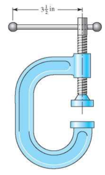
For the screw clamp shown, a force is applied at the end of the handle
- (a) What screw torque will cause the handle to bend permanently?
- (b) What clamping force will the answer to part (a) cause if the collar friction is neglected and if the thread friction is 0.15?
- (c) What clamping force will cause the screw to buckle?
- (d) Are there any other stresses or possible failures to be checked?
Problem 8-7
Expert Solution & Answer
Want to see the full answer?
Check out a sample textbook solution
Chapter 8 Solutions
MECH ENGINEERING DESIGN(LL)+ACCESS
Ch. 8 - A power screw is 25 mm in diameter and has a...Ch. 8 - Using the information in the footnote of Table...Ch. 8 - Show that for zero collar friction the efficiency...Ch. 8 - A single-threaded power screw is 25 mm in diameter...Ch. 8 - The machine shown in the figure can be used for a...Ch. 8 - The press shown for Prob. 8-5 has a rated load of...Ch. 8 - For the screw clamp shown, a force is applied at...Ch. 8 - The C clamp shown in the figure for Prob. 8-7 uses...Ch. 8 - Find the power required to drive a 1.5-in power...Ch. 8 - A single square-thread power screw has an input...
Ch. 8 - Prob. 11PCh. 8 - An M14 2 hex-head bolt with a nut is used to...Ch. 8 - Prob. 13PCh. 8 - A 2-in steel plate and a 1-in cast-iron plate are...Ch. 8 - Repeat Prob. 8-14 with the addition of one 12 N...Ch. 8 - A 2-in steel plate and a 1-in cast-iron plate are...Ch. 8 - Two identical aluminum plates are each 2 in thick,...Ch. 8 - Prob. 18PCh. 8 - A 30-mm thick AISI 1020 steel plate is sandwiched...Ch. 8 - Prob. 20PCh. 8 - Prob. 21PCh. 8 - Prob. 22PCh. 8 - A 2-in steel plate and a 1-in cast-iron plate are...Ch. 8 - An aluminum bracket with a 12-in thick flange is...Ch. 8 - An M14 2 hex-head bolt with a nut is used to...Ch. 8 - A 34 in-16 UNF series SAE grade 5 bolt has a 34-in...Ch. 8 - From your experience with Prob. 8-26, generalize...Ch. 8 - Prob. 28PCh. 8 - Prob. 29PCh. 8 - Prob. 30PCh. 8 - For a bolted assembly with eight bolts, the...Ch. 8 - Prob. 32PCh. 8 - 8-33 to 8-36 The figure illustrates the...Ch. 8 - 8-33 to 8-36 The figure illustrates the...Ch. 8 - 8-33 to 8-36 The figure illustrates the...Ch. 8 - 8-33 to 8-36 The figure illustrates the...Ch. 8 - Prob. 37PCh. 8 - Prob. 38PCh. 8 - 837 to 840 Repeat the requirements for the problem...Ch. 8 - Prob. 40PCh. 8 - 841 to 844 For the pressure vessel defined in the...Ch. 8 - Prob. 42PCh. 8 - Prob. 43PCh. 8 - Prob. 44PCh. 8 - Bolts distributed about a bolt circle are often...Ch. 8 - The figure shows a cast-iron bearing block that is...Ch. 8 - Prob. 47PCh. 8 - Prob. 48PCh. 8 - Prob. 49PCh. 8 - Prob. 50PCh. 8 - 851 to 854 For the pressure cylinder defined in...Ch. 8 - Prob. 52PCh. 8 - 851 to 854 For the pressure cylinder defined in...Ch. 8 - 851 to 854 For the pressure cylinder defined in...Ch. 8 - 855 to 858 For the pressure cylinder defined in...Ch. 8 - 855 to 858 For the pressure cylinder defined in...Ch. 8 - 855 to 858 For the pressure cylinder defined in...Ch. 8 - For the pressure cylinder defined in the problem...Ch. 8 - A 1-in-diameter hot-rolled AISI 1144 steel rod is...Ch. 8 - The section of the sealed joint shown in the...Ch. 8 - Prob. 61PCh. 8 - Prob. 62PCh. 8 - Prob. 63PCh. 8 - Prob. 64PCh. 8 - Using the Goodman fatigue criterion, repeat Prob....Ch. 8 - The figure shows a bolted lap joint that uses SAE...Ch. 8 - Prob. 67PCh. 8 - A bolted lap joint using ISO class 5.8 bolts and...Ch. 8 - Prob. 69PCh. 8 - The figure shows a connection that employs three...Ch. 8 - A beam is made up by bolting together two cold...Ch. 8 - Prob. 72PCh. 8 - Prob. 73PCh. 8 - Prob. 74PCh. 8 - A vertical channel 152 76 (see Table A7) has a...Ch. 8 - The cantilever bracket is bolted to a column with...Ch. 8 - Prob. 77PCh. 8 - The figure shows a welded fitting which has been...Ch. 8 - Prob. 79PCh. 8 - Prob. 80PCh. 8 - Prob. 81P
Knowledge Booster


Learn more about
Need a deep-dive on the concept behind this application? Look no further. Learn more about this topic, mechanical-engineering and related others by exploring similar questions and additional content below.Similar questions
- Compare the angle of twist 1 for a thin-walled circular tube (see figure) calculated from the approximate theory for thin-walled bars with the angle of twist 2 calculated from the exact theory of torsion for circular bars, Express the ratio 12terms of the non-dimensional ratio ß = r/t. Calculate the ratio of angles of twist for ß = 5, 10, and 20. What conclusion about the accuracy of the approximate theory do you draw from these results?arrow_forwardAn aluminum bar has length L = 6 ft and diameter d = 1.375 in. The stress-strain curse for the aluminum is shown in Fig. 1.34. The initial straight, line part of the curve has a slope (modulus of elasticity) of 10.6 × 10⁶ psi. The bar is loaded by tensile forces P = 44.6 k and then unloaded. (a) That is the permanent set of the bar? (b) If the bar is reloaded. what is the proportional limit? hint: Use the concepts illustrated in Figs. l.39b and 1.40.arrow_forwardA solid circulai' aluminum bar AB is fixed at both ends and loaded by a uniformly distributed torque 150N·n/m. The bar has diameter d = 30 mm. Calculate the reactive torques at the supports and the angle of twist at midspan. Assume that G = 28 GPa.arrow_forward
- Repeat Problem 2.3-18, but assume that the bar is made of copper alloy. Calculate the displacements SBand Scif P = 50 kips, L = 5 ft = 3/5 in., b1= 2.75 in., b2= 3 in., and E = 16,000 ksi.arrow_forwardThe piston in an engine is attached to a connecting rod AB, which in turn is connected to a crank arm BC (see figure). The piston slides without friction in a cylinder and is subjected to a force P (assumed to be constant) while moving to the right in the Figure. The connecting rod. with diameter d and length L, is attached at both ends by pins. The crank arm rotates about the axle at C with the pin at B moving in a circle of radius R. The axle at C, which is supported by bearings, exerts a resisting moment M against the crank arm. (a) Obtain a formula for the maximum permissible force Pallow. based upon an allowable compressive stress acin the connecting rod. (b) Calculate the Force Pallowfor the following data:arrow_forward-11 A rubber cube R of a side L = 3 in. and cross- sectional area A = 9 in2 is compressed inside a steel cube S by a force F = 5 lb that applies uniformly distributed pressure to the rubber. Assume E 0.3ksi and,, = 0.45. (a) Calculate the lateral pressure between the rubber and steel (disregard friction between the rubber and the steel, and assume that the steel block is rigid when compared to the rubber). (b) Calculate the change in volume of the rubber.arrow_forward
- A propeller shaft for a small yacht is made of a solid steel bar 104 mm in diameter. The allowable stress in shear is 48 MPa, and the allowable rate of twist is 2.0° in 3.5 meters. (a) Assuming that the shear modulus of elasticity is G = 80 GPa, determine the maximum torque that can be applied to the shaft. (b) Repeat part (a) if the shaft is now hollow with an inner diameter of 5d18. Compare values to corresponding values from part (a).arrow_forward-7 Repeat Problem 2.3-5, but n include the weight of the bar. See Table I-I in Appendix I for the weight density of steel.arrow_forwardA solid brass bar of diameter d = 1.25 in. is subjected to torques T1as shown in part a of the figure. The allowable shear stress in the brass is 12 ksi. What is the maximum permissible value of the torques T1? If a hole of diameter 0.625 in. is drilled longitudinally through the bar, as shown in part b of the figure, what is the maximum permissible value of the torques T2? What is the percent decrease in torque and the percent decrease in weight due to the hole?arrow_forward
- Solve the preceding problem if the diameter is 480 mm, the pressure is 20 MPa, the yield stress in tension is 975 MPa, the yield stress in shear is 460 MPa, the factor of safety is 2,75, the modulus of elasticity is 210 GPa, Poissorfs ratio is 0.28, and the normal strain must not exceed 1190 x 10" . For part (b), assume that the tank thickness is 8 mm and the measured normal strain is 990 x 10~ .arrow_forwardA solid copper bar of circular cross section has length L = 1.25 m and shear modulus of elasticity G = 45 GPa. The bar is designed to carry a 250 N · m torque acting at the ends. If the allowable shear stress is 30 M Pa and the allowable angle of twist between the ends is 2.5°, what is the minimum required diameter?arrow_forwardA hollow, circular, cast-iron pipe (Ec =12,000 ksi) supports a brass rod (Ec= 14,000 ksi} and weight W — 2 kips, as shown. The outside diameter of the pipe is dc= 6 in. (a) If the allowable compressive stress in the pipe is S00O psi and the allowable shortening of the pipe is 0.02 in., what is the minimum required wall thickness trmm? (Include the weights of the rod and steel cap in your calculations.) (b) What is the elongation of the brass rod Srdue to both load Wand its own weight? (c) What is the minimum required clearance h?arrow_forward
arrow_back_ios
SEE MORE QUESTIONS
arrow_forward_ios
Recommended textbooks for you
 Mechanics of Materials (MindTap Course List)Mechanical EngineeringISBN:9781337093347Author:Barry J. Goodno, James M. GerePublisher:Cengage Learning
Mechanics of Materials (MindTap Course List)
Mechanical Engineering
ISBN:9781337093347
Author:Barry J. Goodno, James M. Gere
Publisher:Cengage Learning
Understanding Torsion; Author: The Efficient Engineer;https://www.youtube.com/watch?v=1YTKedLQOa0;License: Standard YouTube License, CC-BY