
MECH ENGINEERING DESIGN(LL)+ACCESS
10th Edition
ISBN: 9781260113952
Author: BUDYNAS
Publisher: MCG
expand_more
expand_more
format_list_bulleted
Videos
Textbook Question
Chapter 8, Problem 78P
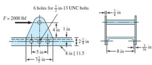
The figure shows a welded fitting which has been tentatively designed to be bolted to a channel so as to transfer the 2000-lbf load into the channel. The channel and the two fitting plates are of hot-rolled stock having a minimum Sy of 42 kpsi. The fitting is to be bolted using six SAE grade 4 shoulder bolts. Assume the bolt threads do not extend into the joint. Check the strength of the design by computing the factor of safety for all possible modes of failure.
Problem 8–78
Expert Solution & Answer
Want to see the full answer?
Check out a sample textbook solution
Students have asked these similar questions
The figure illustrates the connection of a steel cylinder head to a grade 30 cast-iron pressure vessel using N bolts. A confined gasket seal has an effective sealing diameter D. The cylinder stores gas at a maximum pressure pg. For the specifications given in the table for the specific problem assigned, select a suitable bolt length from the preferred sizes in Table A–17, then determine the yielding factor of safety np, the load factor nL, and the joint separation factor n0. See problem number 8-36, and please use the FEA exponential curve-fit for member stiffness.
A right angled bell crank lever is to be
designed to raise a load of 5 kN at the short arm end. The lengths of short and long arms are 100 and 450 mm respectively. The lever and the pins are made of steel 30C8 (S = 400 N/mm2). And the factor of safety is 5.the permissible bearing pressure on the pin is 10 N/mm². The lever has a rectangular cross section and the ratio of width to thickness is 3:1. The length to diameter ratio of the fulcrum pin is 1.25:1. Calculate
(i) The diameter and length of the fulcrum pin
(ii) The dimensions of the cross section.
Determine the safe tensile load for fine series bolts of (a) M 24and (b) M 38. Assume that the bolts are not initially stressed and take the safe tensile stress as 450MPa.
Chapter 8 Solutions
MECH ENGINEERING DESIGN(LL)+ACCESS
Ch. 8 - A power screw is 25 mm in diameter and has a...Ch. 8 - Using the information in the footnote of Table...Ch. 8 - Show that for zero collar friction the efficiency...Ch. 8 - A single-threaded power screw is 25 mm in diameter...Ch. 8 - The machine shown in the figure can be used for a...Ch. 8 - The press shown for Prob. 8-5 has a rated load of...Ch. 8 - For the screw clamp shown, a force is applied at...Ch. 8 - The C clamp shown in the figure for Prob. 8-7 uses...Ch. 8 - Find the power required to drive a 1.5-in power...Ch. 8 - A single square-thread power screw has an input...
Ch. 8 - Prob. 11PCh. 8 - An M14 2 hex-head bolt with a nut is used to...Ch. 8 - Prob. 13PCh. 8 - A 2-in steel plate and a 1-in cast-iron plate are...Ch. 8 - Repeat Prob. 8-14 with the addition of one 12 N...Ch. 8 - A 2-in steel plate and a 1-in cast-iron plate are...Ch. 8 - Two identical aluminum plates are each 2 in thick,...Ch. 8 - Prob. 18PCh. 8 - A 30-mm thick AISI 1020 steel plate is sandwiched...Ch. 8 - Prob. 20PCh. 8 - Prob. 21PCh. 8 - Prob. 22PCh. 8 - A 2-in steel plate and a 1-in cast-iron plate are...Ch. 8 - An aluminum bracket with a 12-in thick flange is...Ch. 8 - An M14 2 hex-head bolt with a nut is used to...Ch. 8 - A 34 in-16 UNF series SAE grade 5 bolt has a 34-in...Ch. 8 - From your experience with Prob. 8-26, generalize...Ch. 8 - Prob. 28PCh. 8 - Prob. 29PCh. 8 - Prob. 30PCh. 8 - For a bolted assembly with eight bolts, the...Ch. 8 - Prob. 32PCh. 8 - 8-33 to 8-36 The figure illustrates the...Ch. 8 - 8-33 to 8-36 The figure illustrates the...Ch. 8 - 8-33 to 8-36 The figure illustrates the...Ch. 8 - 8-33 to 8-36 The figure illustrates the...Ch. 8 - Prob. 37PCh. 8 - Prob. 38PCh. 8 - 837 to 840 Repeat the requirements for the problem...Ch. 8 - Prob. 40PCh. 8 - 841 to 844 For the pressure vessel defined in the...Ch. 8 - Prob. 42PCh. 8 - Prob. 43PCh. 8 - Prob. 44PCh. 8 - Bolts distributed about a bolt circle are often...Ch. 8 - The figure shows a cast-iron bearing block that is...Ch. 8 - Prob. 47PCh. 8 - Prob. 48PCh. 8 - Prob. 49PCh. 8 - Prob. 50PCh. 8 - 851 to 854 For the pressure cylinder defined in...Ch. 8 - Prob. 52PCh. 8 - 851 to 854 For the pressure cylinder defined in...Ch. 8 - 851 to 854 For the pressure cylinder defined in...Ch. 8 - 855 to 858 For the pressure cylinder defined in...Ch. 8 - 855 to 858 For the pressure cylinder defined in...Ch. 8 - 855 to 858 For the pressure cylinder defined in...Ch. 8 - For the pressure cylinder defined in the problem...Ch. 8 - A 1-in-diameter hot-rolled AISI 1144 steel rod is...Ch. 8 - The section of the sealed joint shown in the...Ch. 8 - Prob. 61PCh. 8 - Prob. 62PCh. 8 - Prob. 63PCh. 8 - Prob. 64PCh. 8 - Using the Goodman fatigue criterion, repeat Prob....Ch. 8 - The figure shows a bolted lap joint that uses SAE...Ch. 8 - Prob. 67PCh. 8 - A bolted lap joint using ISO class 5.8 bolts and...Ch. 8 - Prob. 69PCh. 8 - The figure shows a connection that employs three...Ch. 8 - A beam is made up by bolting together two cold...Ch. 8 - Prob. 72PCh. 8 - Prob. 73PCh. 8 - Prob. 74PCh. 8 - A vertical channel 152 76 (see Table A7) has a...Ch. 8 - The cantilever bracket is bolted to a column with...Ch. 8 - Prob. 77PCh. 8 - The figure shows a welded fitting which has been...Ch. 8 - Prob. 79PCh. 8 - Prob. 80PCh. 8 - Prob. 81P
Knowledge Booster


Learn more about
Need a deep-dive on the concept behind this application? Look no further. Learn more about this topic, mechanical-engineering and related others by exploring similar questions and additional content below.Similar questions
- Question No.15: Design muff coupling to connect two steel shafts transmitting 40 kW at 350 rpm. The material for shafts and key is plain carbon steel for which allowable shear and crushing stresses are 40 MPa and 80 MPa respectively. The material for muff is cast iron for which allowable shear stress is 15 Mpaarrow_forwardDraw the Mohr Circle and mark important points for a rod under pure tensile load & torsionarrow_forwardA flange coupling connects two 2” diameter shafts. The flanges are fitted with 6 bolts of SAE 1040 steel on a 7” bolt circle. The shafts runs at 300 rpm and transmits 45 hp. Assume a factor of safety of 5, ultimate tension of 70,000 psi, and ultimate shear of 55,000 psi. Determine: a) The torque transmitted, in-lbs b) The force applied per bolt, lbs c) The diameter of the bolt required, in d) The thickness of flanged to be used, inarrow_forward
- 3. Design a compression coupling for a shaft to transmit 1300 N-m. The allowable shear stress for the shaft and key is 40 MPa and the number of bolts connecting the two halves are 4. The permissible tensile stress for the bolts material is 70 MPa. The coefficient of friction between the muff and the shaft surface may be taken as 0.3.arrow_forwardA rigid coupling with 30 inches of bolt circle diameter transmits a torque of 18,000 lb-in. The coupling material has a yield strength of 90,000 psi. The coupling is fastened by six bolts. Assume design factor of N=3 Calculate the diameter of each bolt.arrow_forwardUse LRFD and design a 13-foot-long tension member and its connection for a service dead load of 8 kips and a service live load of 24 kips. No slip of the connection is permitted. The connection will be to a 3⁄8-inch-thick gusset plate, as shown in Figure . Use a single angle for the tension member. Use Group A bolts and A572 Grade 50 steel for both the tension member and the gusset plate.arrow_forward
- Design a typical rigid flange coupling for connecting a motor and a centrifugal pump shafts. The coupling needs to transmit 15 KW at 1000 rpm. The allowable shear stresses of the shaft, key and bolt materials are 60 MPa, 50 MPa and 25 MPa respectively. The shear modulus of the shaft material may be taken as 84GPa. The angle of twist of the shaft should be limited to 1 degree in 20 times the shaft diameter. Note: show complete solutionarrow_forwardA semi-elliptic spring used for automobile suspension, consists of two extra full-length leaves and eight graduated-length leaves, including the master leaf. The centre-to centre distance between the two eyes is 1 m. The leaves are made of steel 55Si2Mo90 (Syt = 1500 N/mm2and E = 207000 N/mm2) and the factor of safety is 2. The maximum spring load is 30 kN. The leaves are pre- stressed so as to equalize stresses in all leaves under maximum load. Determine the dimensions of the cross-section of the leaves and the deflection at the end of the spring.arrow_forwardDesign a rigid flange coupling to transmit a torque of 250N-m between two coaxial shafts. The shaft is made of alloy steel, flanges out of cast iron and bolts out of steel. Four bolts are used to couple the flanges. The shafts are keyed to the flange hub. The permissible stresses are given below: Shear stress on shaft =100MPa Bearing or crushing stress on shaft =250MPa Shear stress on keys =100MPa Bearing stress on keys = 250MPa Shearing stress on cast iron = 200Mpa Shear stress on bolts =100MPa Torque = 257N-marrow_forward
- Design a rigid flange coupling to transmit a torque of 257N-m between two coaxial shafts. The shaft is made of alloy steel, flanges out of cast iron and bolts out of steel. Four bolts are used to couple the flanges. The shafts are keyed to the flange hub. The permissible stresses are given below: Shear stress on shaft =100MPa Bearing or crushing stress on shaft =250MPa Shear stress on keys =100MPa Bearing stress on keys = 250MPa Shearing stress on cast iron = 200Mpa Shear stress on bolts =100MPa Answer in Word pleasearrow_forwardA belt is to transmit 50 kW power to a machine. The sheave is 10 inches in diameter and turns at 1200 rpm, while the larger sheave turns at 500 rpm. Determine the design HP if a service factor of 1.35 and a correction factor of 0.85.arrow_forwardA rigid block is supported by two cables having the same diameter of 4 mm. Cable S1 is made of AISI 1050 cold drawn steel with E=200,000 MPa, Sy=580 MPa, and Sult=690 MPa; cable S2 is made of AISI 1020 cold drawn steel with E=200,000 MPa, Sy=390 MPa, and Sult=470 MPa. Determine the maximum number of cycles n3 due to the following history of P.arrow_forward
arrow_back_ios
SEE MORE QUESTIONS
arrow_forward_ios
Recommended textbooks for you
 Elements Of ElectromagneticsMechanical EngineeringISBN:9780190698614Author:Sadiku, Matthew N. O.Publisher:Oxford University Press
 Mechanics of Materials (10th Edition)Mechanical EngineeringISBN:9780134319650Author:Russell C. HibbelerPublisher:PEARSON
 Thermodynamics: An Engineering ApproachMechanical EngineeringISBN:9781259822674Author:Yunus A. Cengel Dr., Michael A. BolesPublisher:McGraw-Hill Education
 Control Systems EngineeringMechanical EngineeringISBN:9781118170519Author:Norman S. NisePublisher:WILEY
 Mechanics of Materials (MindTap Course List)Mechanical EngineeringISBN:9781337093347Author:Barry J. Goodno, James M. GerePublisher:Cengage Learning
 Engineering Mechanics: StaticsMechanical EngineeringISBN:9781118807330Author:James L. Meriam, L. G. Kraige, J. N. BoltonPublisher:WILEY
Elements Of Electromagnetics
Mechanical Engineering
ISBN:9780190698614
Author:Sadiku, Matthew N. O.
Publisher:Oxford University Press
Mechanics of Materials (10th Edition)
Mechanical Engineering
ISBN:9780134319650
Author:Russell C. Hibbeler
Publisher:PEARSON
Thermodynamics: An Engineering Approach
Mechanical Engineering
ISBN:9781259822674
Author:Yunus A. Cengel Dr., Michael A. Boles
Publisher:McGraw-Hill Education
Control Systems Engineering
Mechanical Engineering
ISBN:9781118170519
Author:Norman S. Nise
Publisher:WILEY
Mechanics of Materials (MindTap Course List)
Mechanical Engineering
ISBN:9781337093347
Author:Barry J. Goodno, James M. Gere
Publisher:Cengage Learning
Engineering Mechanics: Statics
Mechanical Engineering
ISBN:9781118807330
Author:James L. Meriam, L. G. Kraige, J. N. Bolton
Publisher:WILEY
Mechanical SPRING DESIGN Strategy and Restrictions in Under 15 Minutes!; Author: Less Boring Lectures;https://www.youtube.com/watch?v=dsWQrzfQt3s;License: Standard Youtube License