Videos
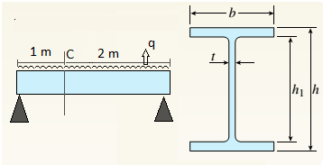
A beam with a wide-flange cross section (see figure) has the following dimensions: b = 5 in., t = 0.5 in,, ft = 12 in., and /?, = 10.5 in. The beam is simply supported with span length L = 10 ft and supports a uniform load q = 6 kips/fL
Calculate the principal stresses *rl and
[|] JA
3 ft from the left-hand support at each of the following locations: (a) the bottom of the beam, (b) the bottom of the web, and (c) the neutral axis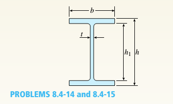
(a).
Find principal stresses and maximum shear stress at top of beam.
Answer to Problem 8.4.15P
Principal stresses
Maximum shear stress
Explanation of Solution
Given Information:
Beam length
Uniform load
Concept Used:
Bending stress
Shear stress
Principal normal stresses
Maximum shear stress
So bending moment at point
Shear force at point
Moment of inertia,
First moment of area at the top of beam shall be zero,
So bending stress at top,
And shear stress at that point,
For this situation no stress in
Principal normal stresses are given by following equation,
Maximum shear stress,
Conclusion:
Hence we get,
Principal stresses
Maximum shear stress
(b).
Find principal stresses and maximum shear stress at top of web.
Answer to Problem 8.4.15P
Principal stresses
Maximum shear stress
Explanation of Solution
Given Information:
Beam length
Uniform load
Concept Used:
Bending stress
Shear stress
Principal normal stresses
Maximum shear stress

So bending moment at point
Shear force at point
Moment of inertia,
First moment of area of flange,
So bending stress at top of web,
And shear stress at that point,
For this situation no stress in
Principal normal stresses are given by following equation,
Maximum shear stress,
Conclusion:
Hence we get,
Principal stresses
Maximum shear stress
(c).
Find principal stresses and maximum shear stress at neutral axis.
Answer to Problem 8.4.15P
Principal stresses
Maximum shear stress
Explanation of Solution
Given Information:
Beam length
Uniform load
Concept Used:
Bending stress
Shear stress
Principal normal stresses
Maximum shear stress

So bending moment at point
Shear force at point
Moment of inertia,
First moment of area for the section above the neutral axis,
So bending stress at neutral axis,
And shear stress at that point,
For this situation no stress in
Principal normal stresses are given by following equation,
Maximum shear stress,
Conclusion:
Hence we get,
Principal stresses
Maximum shear stress
Want to see more full solutions like this?
Chapter 8 Solutions
Mechanics of Materials - Text Only (Looseleaf)


- A reinforced concrete T-beam (see figure) is acted on by a positive bending moment of M = 175 kip-ft. Steel reinforcement consists of four bars of 1.41-inch diameter. The modulus of elasticity for the concrete is Ec= 3000 ksi while that of the steel is £s = 29,000 ksi. Let b = 48 im, rf = 4 in., bw=15 in,, and d = 24 in, Find the maximum stresses in steel and concrete, If allowable stresses for concrete and steel are o"ac = 1400 psi and tr^ =18 ksi, respectively, what is the maximum permissible positive bending moment?arrow_forwardA W 310 x 52 steel beam is subjected to a point load P = 45 kN and a transverse load V = 20 kN at B. The beam has length L =2m.(a) Calculate the principal normal stresses and the maximum shear stress on element D located on the web right below the top flange and near the fixed support. Neglect the weight of the beam, (b) Repeat Part a atcentroid C (sec figure). See Table F-l(b), Appendix F, for beam propertiesarrow_forwardA steel beam of length L = 16 in. and cross-sectional dimensions h = 0.6 in. and h = 2 in. (see figure) supports a uniform load of intensity if = 240 lb/in., which includes the weight of the beam. Calculate the shear stresses in the beam (at the cross section of maximum shear force) at points located 1/4 in., 1/2 in., 3/4 in., and I in, from the top surface of the beam. From these calculations, plot a graph showing the distribution of shear stresses from top to bottom of the beam.arrow_forward
- A cantilever beam(Z, = 6 ft) with a rectangular cross section (/> = 3.5 in., h = 12 in.) supports an upward load P = 35 kips at its free end. (a) Find the state of stress ((7T, o^., and r in ksi) on a plane-stress element at L/2 that is i/ = 8 in. up from the bottom of the beam. Find the principal normal stresses and maximum shear stress. Show these stresses on sketches of properly oriented elements. (b) Repeat part (a) if an axial compressive centroidal load N = 40 kips is added at Barrow_forwardA W 12 x 35 steel cantilever beam is subjected to an axial load P = 10 kips and a transverse load V = 15 kips. The beam has length L = 6 ft, (a) Calculate the principal normal stresses and the maximum shear stress for an clement located at C near the fixed support. Neglect the weight of the beam, (b) Repeat Part a for point D which is 4 in. above point C (see figure). See Table F-l(a), Appendix F, for beam properties.arrow_forwardA simple beam of span length 3.2 m carries a uniform load of intensity 48 kN/m, The cross section of the beam is a hollow box with wood flanges and steel side plates, as shown in the figure. The wood flanges are 75 mm x 100 mm in cross section, and the steel plates are 300 mm deep. What is the required thickness t of the steel plates if the allowable stresses are 120 M Pa for the steel and 6,5 M Pa for the wood? (Assume that the moduli of elasticity for the steel and wood are 210 GPa and 10 GPa, respectively, and disregard the weight of the beam.)arrow_forward
- The cantilever beam AB shown in the figure is an S6 × 12.5 steel I-beam with E = 30 × 106 psi. The simple beam DE is a wood beam 4 in. x 12 in. (nominal dimensions) in cross section with E = 1.5 x 10⁶ psi. A steel rod AC of diameter 0.25 in., length 10 ft, and E = 30 x 106 psi serves as a hanger joining the two beams. The hanger fits snugly between the beams before the uniform load is applied to beam DE. Determine the tensile force Fin the hanger and the maximum bending moments MABand MDEin the two beams due to the uniform load, which has an intensity q = 400 lb/ft. Hint: To aid in obtaining the maximum bending moment in beam DE, draw the shear-force and bending-moment diagrams.arrow_forwardA beam of wide-flange shape, W 8 x 28, has the cross section shown in the figure. The dimensions are b = 6.54 in., h = 8.06 in., fw = 0.285 in., and tf = 0.465 in.. The loads on the beam produce a shear force V = 7.5 kips at the cross section under consideration. Use center line dimensions to calculate the maximum shear stress raiaxin the web of the beam. Use the more exact analysis of Section 5,10 in Chapter 5 to calculate the maximum shear stress in the web of the beam and compare it with the stress obtained in part .arrow_forwardA W 12 x 50 steel wide-flange beam and a segment of a 4-inch thick concrete slab (see figure) jointly resist a positive bending moment of 95 kip-ft. The beam and slab are joined by shear connectors that are welded to the steel beam. (These connectors resist the horizontal shear at the contact surface.) The moduli of elasticity of the steel and the concrete are in the ratio 12 to 1. Determine the maximum stresses r1 and xtin the steel and concrete, respectively. Note: See Table F-l(a) of Appendix F for the dimensions and properties of the steel beam.arrow_forward
- A W 12 x 35 steel beam is fixed at A. The beam has length L = 6 ft and is subjected to a linearly varying distributed load with peak intensity q0=830 lb/ft. Calculate the state of plane stress at point C located 3 in, below the top of the beam at mid-span. Also find the principal normal stresses and the maximum shear stress at C. Include the weight of the beam. Sec Table F-l(a), Appendix F, for beam propertiesarrow_forwardA reinforced concrete slab (see figure) is reinforced with 13-mm bars spaced 160 mm apart at d = 105 mm from the top of the slab. The modulus of elasticity for the concrete is Ec= 25 GPa, while that of the steel is £s = 200 G Pa. Assume that allowable stresses for concrete and steel arecrac = 9.2 MPa and us = 135 MPa. l()5 mm Find the maximum permissible positive bending moment for a l-m wide strip of the slab. What is the required area of steel reinforcement, A^ if a balanced condition must be achieved? What is the allowable positive bending moment? (Recall that in a balanced design, both steel and concrete reach allowable stress values simultaneously under the design moment.)arrow_forwardA W 200 x 41.7 wide-flange beam (see Table F-l(b), Appendix F) is simply supported with a span length of 2.5 m (see figure). The beam supports a concentrated load of 100 kN at 0.9 m from support B. At a cross section located 0,7 m from the left-hand support, determine the principal stresses tr, and 2and the maximum shear stress rnMJt at each of the following locations: (a) the top of the beam, (b) the top of the web, and (c) the neutral axis,arrow_forward
 Mechanics of Materials (MindTap Course List)Mechanical EngineeringISBN:9781337093347Author:Barry J. Goodno, James M. GerePublisher:Cengage Learning