
Concept explainers
Videos
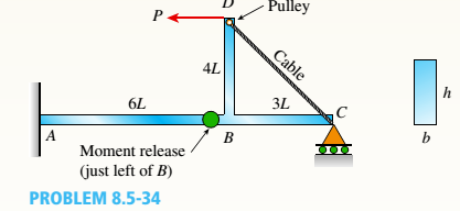
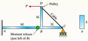
A compound beam ABCD has a cable with force P anchored at C The cable passes over a pulley at D, and force P acts in the —x direction, There is a moment release just left of B. Neglect the self-weight of the beam and cable. Cable force P = 450 N and dimension variable L = 0.25 m. The beam has a rectangular cross section (b = 20 mm, it = 50 mm).
(a) Calculate the maximum normal stresses and maximum in-plane shear stress on the bottom surface of the beam at support A.
(b) Repeat part (a) for a plane stress element located at mid-height of the beam at A.
(c) If the maximum tensile stress and maximum in-plane shear stress at point A are limited to 90 MPa and 42 MPa, respectively, what is the largest permissible value of the cable force P?
(a)
The maximum normal stresses and maximum in-plane shear stress on the bottom of the beam at fixed support A.
Answer to Problem 8.5.34P
Maximum normal stresses,
Maximum in-plane shear stress
Explanation of Solution
Given information: A compound beam ABCD has a cable having force P anchored at C as shown in the figure below:
Cable force
Dimension variable
The cross section of the beam
To calculate the maximum normal stress and in-plane shear stress first taken the cross-sectional properties of the beam.
Area of the rectangular beam
Moment of inertia of the rectangular beam is
Now reactions at fixed support A
Horizontal force
Shear force
And moment at point A,
Now, maximum normal stresses on the bottom of the beam at A is,
And at principle plane where there is maximum normal stress the shear stress is zero. So,
Principle stresses:
Maximum in-plane shear stress
(b)
Maximum stresses located at the mid-height of the beam at A.
Answer to Problem 8.5.34P
Maximum normal stresses,
Maximum in-plane shear stress
Explanation of Solution
Given information: A compound beam ABCD has a cable having force P anchored at C as shown in the figure below:

Cable force
Dimension variable
The cross section of the beam
Area of the rectangular beam
Moment of inertia of the rectangular beam is
Now reactions at fixed support A
Horizontal force
Shear force
The maximum normal stresses at the mid-point of the beam at A is,
And,
Principle stresses:
Maximum in-plane shear stress
(c)
The maximum permissible value of the cable force P.
Answer to Problem 8.5.34P
Maximum permissible value of P
Explanation of Solution
Given information: A compound beam ABCD has a cable having force P anchored at C as shown in the figure below:

Dimension variable
Maximum tensile stress at point A,
Maximum shear stress at point A,
The cross section of the beam
Area of the rectangular beam
Moment of inertia of the rectangular beam is
And moment at point A,
In the above figure the maximum cable force P is controlled by the tensile and maximum shear force at the bottom of the beam at point A.
Hence, tensile stress
Then,
By substituting the values we get,
And,
Then,
Conclusion:
Hence from the obtained values the maximum permissible value of the force P is
Want to see more full solutions like this?
Chapter 8 Solutions
Mechanics of Materials, SI Edition


- Beam ABC with an overhang BC is subjected to a linearly varying distributed load on span AB with peak: intensity q0= 2500 N/m and a point load P = 1250 N applied at C. The beam has a width ft = 100 mm and depth h = 200 mm. Find the state of plane stress at point D located 150 mm below the top of the beam and 0.2 m to the left of point B. Also find the principal stresses at D>Neglect the weight of the beam.arrow_forwardA cantilever beam(Z, = 6 ft) with a rectangular cross section (/> = 3.5 in., h = 12 in.) supports an upward load P = 35 kips at its free end. (a) Find the state of stress ((7T, o^., and r in ksi) on a plane-stress element at L/2 that is i/ = 8 in. up from the bottom of the beam. Find the principal normal stresses and maximum shear stress. Show these stresses on sketches of properly oriented elements. (b) Repeat part (a) if an axial compressive centroidal load N = 40 kips is added at Barrow_forwardA W 12 x 35 steel beam is fixed at A. The beam has length L = 6 ft and is subjected to a linearly varying distributed load with peak intensity q0=830 lb/ft. Calculate the state of plane stress at point C located 3 in, below the top of the beam at mid-span. Also find the principal normal stresses and the maximum shear stress at C. Include the weight of the beam. Sec Table F-l(a), Appendix F, for beam propertiesarrow_forward
- A bimetallic beam used in a temperature-control switch consists of strips of aluminum and copper bonded together as shown in the figure, which is a cross-sectional view. The width of the beam is LO in,, and each strip has a thickness of 1/16 in. Under the action of a bending moment M = 12 lb-in, acting about the z axis, what are the maximum stresses aaand ecin the aluminum and copper, respectively? (Assume fA, = 10,5 x l0 psi and ecu= 16,8 × 10⁶ psi,)arrow_forwardA plastic bar of rectangular cross section (ft = 1.5 in. and h = 3 in.) fits snugly between rigid supporls at room temperature (68oF) but with no initial stress (see Figure). When the temperature of the bar is raised to 160oF, the compressive stress on an inclined plane pq at mid-span becomes 1700 psi. (a) What is the shear stress on plane pq? (Assume a = 60 × 10-6/*t and E = 450 × 103psi.) (b) Draw a stress element oriented to plane pq and show the stresses acting on all laces of this element. (c) If the allowable normal stress is 3400 psi and the allowable shear stress is 1650 psi. what is the maximum load P (in the positive x direction), which can be added at the quarter point (in addition to thermal effects given) without exceeding allowable stress values in the bar?arrow_forwardA reinforced concrete slab (see figure) is reinforced with 13-mm bars spaced 160 mm apart at d = 105 mm from the top of the slab. The modulus of elasticity for the concrete is Ec= 25 GPa, while that of the steel is £s = 200 G Pa. Assume that allowable stresses for concrete and steel arecrac = 9.2 MPa and us = 135 MPa. l()5 mm Find the maximum permissible positive bending moment for a l-m wide strip of the slab. What is the required area of steel reinforcement, A^ if a balanced condition must be achieved? What is the allowable positive bending moment? (Recall that in a balanced design, both steel and concrete reach allowable stress values simultaneously under the design moment.)arrow_forward
- A W 12 x 35 steel cantilever beam is subjected to an axial load P = 10 kips and a transverse load V = 15 kips. The beam has length L = 6 ft, (a) Calculate the principal normal stresses and the maximum shear stress for an clement located at C near the fixed support. Neglect the weight of the beam, (b) Repeat Part a for point D which is 4 in. above point C (see figure). See Table F-l(a), Appendix F, for beam properties.arrow_forwardA simple beam of span length 3.2 m carries a uniform load of intensity 48 kN/m, The cross section of the beam is a hollow box with wood flanges and steel side plates, as shown in the figure. The wood flanges are 75 mm x 100 mm in cross section, and the steel plates are 300 mm deep. What is the required thickness t of the steel plates if the allowable stresses are 120 M Pa for the steel and 6,5 M Pa for the wood? (Assume that the moduli of elasticity for the steel and wood are 210 GPa and 10 GPa, respectively, and disregard the weight of the beam.)arrow_forwardA weight W = 4500 lb falls from a height h onto a vertical wood pole having length L = 15 ft, diameter d = 12 in., and modulus of elasticity E = 1.6 × 10⁶ psi (see figure). If the allowable stress in the wood under an impact load is 2500 psi. what is the maximum permissible height h?arrow_forward
- Segments A B and BCD of beam A BCD are pin connected at x = 4 m. The beam is supported by a sliding support at A and roller supports at C and D (see figure). A triangularly distributed load with peak intensity of SO N/m acts on EC. A concentrated moment is applied at joint D. (a) Find reactions at supports A, C, and D. (b) Find internal stress resultants N, Y, and Mat x = 5m. (c) Repeat parts (a) and (b) for die case of the roller support at C replaced by a linear spring of stiffness kr™ 200 kN/m (see figure).arrow_forwardA steel beam of length L = 16 in. and cross-sectional dimensions h = 0.6 in. and h = 2 in. (see figure) supports a uniform load of intensity if = 240 lb/in., which includes the weight of the beam. Calculate the shear stresses in the beam (at the cross section of maximum shear force) at points located 1/4 in., 1/2 in., 3/4 in., and I in, from the top surface of the beam. From these calculations, plot a graph showing the distribution of shear stresses from top to bottom of the beam.arrow_forwardSolve the preceding problem for a box beam with dimensions h = 0.5 m, h = 0.18 m, and t = 22 mm. The yield stress of the steel is 210 MPa.arrow_forward
 Mechanics of Materials (MindTap Course List)Mechanical EngineeringISBN:9781337093347Author:Barry J. Goodno, James M. GerePublisher:Cengage Learning