
CODE/MINES MECHANICS MATERIALS >IC<
16th Edition
ISBN: 9781323168950
Author: HIBBELER
Publisher: PEARSON C
expand_more
expand_more
format_list_bulleted
Concept explainers
Videos
Textbook Question
Chapter 8.1, Problem 8.17P
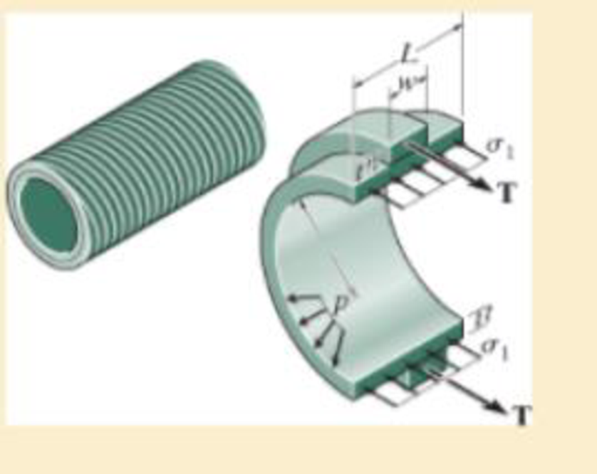
In order to increase the strength of the pressure vessel, filament winding of the same material is wrapped around the circumference of the vessel as shown. If the pretension in the filament is T and the vessel is subjected to an internal pressure p, determine the hoop stresses in the filament and in the wall of the vessel. Use the free-body diagram shown, and assume the filament winding has a thickness t′ and width w for a corresponding length L of the vessel.
Expert Solution & Answer
Want to see the full answer?
Check out a sample textbook solution
Students have asked these similar questions
The cylindrical tank with a spherical endcap has an outer radius of 2 m and a wall thickness of 25 mm. If the tank is pressurized to 1.5 MPa, determine the longitudinal and circumferential stresses in the cylinder, and the stress in the endcap.
Air is pumped into the steel thin-walled pressure vessel at C. If the ends of the vessel are closed using two pistons connected by a rod AB, determine the increase in the diameter of the pressure vessel when the internal gage pressure is 5 MPa. Also, what is the tensile stress in rod AB if it has a diameter of 100 mm? The inner radius of the vessel is 400 mm, and its thickness is 10 mm. Est = 200 GPa and nst = 0.3.
The cylindrical tank with a spherical end cap has an outer radius of 2 m and a
wall thickness of 50 mm. If the tank is pressurized to 3.5 MPa, determine the
longitudinal and circumferential stresses in the cylinder, and the stress in the
end cap.
(Show free body diagram and complete solution)
Chapter 8 Solutions
CODE/MINES MECHANICS MATERIALS >IC<
Ch. 8.1 - If it is subjected to an internal pressure of p =...Ch. 8.1 - If it is subjected to an internal pressure of p =...Ch. 8.1 - The thin-walled cylinder can be supported in one...Ch. 8.1 - If the inner diameter of the tank is 22 in., and...Ch. 8.1 - Prob. 8.5PCh. 8.1 - 8–6. If the flow of water within the pipe in Prob....Ch. 8.1 - A boiler is constructed of 8-mm-thick steel plates...Ch. 8.1 - 88. The steel water pipe has an inner diameter of...Ch. 8.1 - The steel water pipe has an inner diameter of 12...Ch. 8.1 - The A-36-steel band is 2 in. wide and is secured...
Ch. 8.1 - Two hemispheres having an inner radius of 2 ft and...Ch. 8.1 - A pressure-vessel head is fabricated by welding...Ch. 8.1 - An A-36-steel hoop has an inner diameter of 23.99...Ch. 8.1 - The ring, having the dimensions shown, is placed...Ch. 8.1 - The inner ring A has an inner radius r1 and outer...Ch. 8.1 - *8–16. A closed-ended pressure vessel is...Ch. 8.1 - In order to increase the strength of the pressure...Ch. 8.2 - Show the results on the left segment.Ch. 8.2 - Show the stress that each of these loads produce...Ch. 8.2 - Fundamental Problems F81. Determine the normal...Ch. 8.2 - Show the results in a differential element at the...Ch. 8.2 - Determine the state of stress at point A on the...Ch. 8.2 - Determine the magnitude of the load P that will...Ch. 8.2 - Determine the state of stress at point B. Show the...Ch. 8.2 - Determine the state of stress at point A on the...Ch. 8.2 - Determine the state of stress at point A on the...Ch. 8.2 - Show the results in a differential element at the...Ch. 8.2 - Determine the shortest distance d to the edge of...Ch. 8.2 - 8–19. Determine the maximum and minimum normal...Ch. 8.2 - *8–20. Determine the maximum and minimum normal...Ch. 8.2 - Also, plot the normal-stress distribution over the...Ch. 8.2 - 8–22. The clamp is made from members AB and AC,...Ch. 8.2 - 8–23. The clamp is made from members AB and AC,...Ch. 8.2 - Prob. 8.24PCh. 8.2 - 8–25. The bearing pin supports the load of 700 lb....Ch. 8.2 - Determine the maximum normal stress on the cross...Ch. 8.2 - If the wood has an allowable normal stress of...Ch. 8.2 - *8–28. The cylindrical post, having a diameter of...Ch. 8.2 - 8–29. Determine the maximum load P that can be...Ch. 8.2 - If the force of 100 N is applied to the handles,...Ch. 8.2 - 8–31. Determine the smallest distance d to the...Ch. 8.2 - *8–32. The horizontal force of P = 80 kN acts at...Ch. 8.2 - 8–33. The control lever is subjected to a...Ch. 8.2 - 8–34. The control lever is subjected to a...Ch. 8.2 - 8–35. The tubular shaft of the soil auger is...Ch. 8.2 - Determine the state of stress at point A on the...Ch. 8.2 - Determine the state of stress at point B on the...Ch. 8.2 - Determine the state of stress acting at point D....Ch. 8.2 - Determine the state of stress acting at point E....Ch. 8.2 - Prob. 8.40PCh. 8.2 - Prob. 8.41PCh. 8.2 - 8–42. Determine the state of stress at point A on...Ch. 8.2 - 8–43. Determine the state of stress at point B on...Ch. 8.2 - Neglect the weight of the block.Ch. 8.2 - Neglect the weight of the block.Ch. 8.2 - Prob. 8.46PCh. 8.2 - Prob. 8.47PCh. 8.2 - Prob. 8.48PCh. 8.2 - Prob. 8.49PCh. 8.2 - The coiled spring is subjected to a force P. If we...Ch. 8.2 - Specify the region to which this load can be...Ch. 8.2 - Determine the smallest force P that can be applied...Ch. 8.2 - 8–53. The 1-in.-diameter rod is subjected to the...Ch. 8.2 - 8–54. The 1-in.-diameter rod is subjected to the...Ch. 8.2 - 8–55. Determine the state of stress at point A on...Ch. 8.2 - *8–56. Determine the state of stress at point B on...Ch. 8.2 - Determine the stress components at points A and B...Ch. 8.2 - Determine the stress components at points C and D...Ch. 8.2 - 8–59. If P = 60 kN, determine the maximum normal...Ch. 8.2 - *8–60. Determine the maximum allowable force P, if...Ch. 8.2 - If the force at the ram on the clamp at D is P= 8...Ch. 8.2 - Determine the maximum ram force P that can be...Ch. 8.2 - and an outer radius of 3.00 in. If the face of the...Ch. 8.2 - for points E and F.Ch. 8.2 - 8–65. Determine the state of stress at point A on...Ch. 8.2 - 8–66. Determine the state of stress at point B on...Ch. 8.2 - 8–67. The metal link is subjected to the axial...Ch. 8.2 - *8–68. The bar has a diameter of 40 mm. If it is...Ch. 8.2 - 8–69. Solve Prob. 8-68 for point B.
Ch. 8.2 - Determine the stress components at point A. Sketch...Ch. 8.2 - for the stress components at point B.Ch. 8.2 - Determine the state of stress at point A at...Ch. 8.2 - Determine the state of stress at point B at...Ch. 8 - If it supports a cable loading of 800 lb,...Ch. 8 - Determine the state of stress at point E on the...Ch. 8 - Determine the state of stress at point F on the...Ch. 8 - If it has a mass of 5 kg/m, determine the largest...Ch. 8 - 8–78. Solve Prob. 8–77 if the bar has a circular...Ch. 8 - The suspender arm AE has a square cross-sectional...Ch. 8 - Prob. 8.80RPCh. 8 - 8–81. The hydraulic cylinder has an inner diameter...Ch. 8 - If the cross section of the femur at section aa...Ch. 8 - 8-83. Air pressure in the cylinder is increased by...Ch. 8 - *8-84. Determine the maximum force P that can be...Ch. 8 - and is used to support the vertical reactions of...Ch. 8 - and is used to support the vertical reactions of...
Knowledge Booster


Learn more about
Need a deep-dive on the concept behind this application? Look no further. Learn more about this topic, mechanical-engineering and related others by exploring similar questions and additional content below.Similar questions
- Determine the maximum distance d to the edge of the plate at which the force P can be applied so that it produces no compressive stresses on the plate at section a–a. The plate has a thickness of 20 mm and P acts along thecenterline of this thickness.arrow_forwardAir pressure in the cylinder is increased by exerting forces P = 3 kN on the two pistons, each having a radius of 45 mm. The cylinder is shown in the figure below. If the cylinder has a wall thickness of 2 Mm, determine the circumferential stress in the wall of the cylinder. Express your answer to three significant figures and include appropriate units.arrow_forwardThe tank of the air compressor is subjected to an internal pressure of 90 psi. If the inner diameter of the tank is 22 in., and the wall thickness is 0.25 in., determine the stress components acting at point A. Draw a volume element of the material at this point, and show the results on the element.arrow_forward
- When the temperature is at 30°C, the A-36 steel pipe fits snugly between the two fuel tanks. When fuel flows through the pipe, the temperatures at ends A and B rise to 130°C and 80°C, respectively. If the temperature drop along the pipe is linear, determine the average normal stress developed in the pipe. Assume each tank provides rigid support at A and B.arrow_forwardDetermine the normal stress in a basketball of 9.5-in. outer diameter and 0.125-in. wall thickness that is inflated to a gage pressure of 9 psi.arrow_forwardThe distributed loading is applied to the rigid beam, which is supported by the three bars. Each bar has a cross-sectional area of 1.25 in2 and is made from a material having a stress–strain diagram that can be approximated bythe two line segments. If a load of w = 25 kip>ft is applied to the beam, determine the stress in each bar and the vertical displacement of the beam.arrow_forward
- A thin hollow spherical container has a diameter 1 m and a thickness of 4 mm is subjected to an internal pressure. Determine the internal pressure the tensile stress of the element in the sphere is 500 kPa.arrow_forwardThe ring, with dimensions shown, is placed over a flexible membrane which is pumped up with a pressure p. The thickness r,-r; is small compared to r; (a) Determine the axial force F in the ring in terms of p, w and r;. Hint: Consider a FBD by cutting the ring+membrane in two. (b) Determine the hoop stress in the ring. (c) Determine the hoop strain in the ring. The modulus of elasticity for the ring is E. (d) Relate the hoop strain to the change in the inner radius of the ring after this pressure is applied, and use this to get the change in the inner radius in terms of p, E, w, r, and ri- (PLEASE ANSWER ASAP AND CORRECTLY)!arrow_forwardThe thin-walled pipe has an inner diameter of 0.5 in. and a thickness of 0.025 in. If it is subjected to an internal pressure of 500 psi and the axial tension and torsional loadings shown, determine the principal stress at a point on the surface of the pipe.arrow_forward
- A rubber bolt is inflated to apressure of 65kPa. At that pressure, te diameter ofthe ball is 240mm and the wall thickness is 1.25mm. The rubber has a modulus ofElasticity = 3.7 MPa and Poisson’s ratio v=0.48. Determine the maximum stress in theball if its stress is half that of the cylinder.arrow_forwardThe steel water pipe has an inner diameter of 12 in. and a wall thickness of 0.25 in. If the valve A is closed and the water pressure is 300 psi, determine the longitudinal and hoop stress developed in the wall of the pipe at point B. Draw the state of stress on a volume element located on the wall.arrow_forwardA cylindrical propane tank has an outside diameter of 3.25 m. If the allowable hoop stress is 100 MPa and the allowable axial or longitudinal stress is 45 MPa, determine the minimum thickness of the pipe when the internal pressure that can be applied to the tank is 1.25 MPa.arrow_forward
arrow_back_ios
SEE MORE QUESTIONS
arrow_forward_ios
Recommended textbooks for you
 Elements Of ElectromagneticsMechanical EngineeringISBN:9780190698614Author:Sadiku, Matthew N. O.Publisher:Oxford University Press
 Mechanics of Materials (10th Edition)Mechanical EngineeringISBN:9780134319650Author:Russell C. HibbelerPublisher:PEARSON
 Thermodynamics: An Engineering ApproachMechanical EngineeringISBN:9781259822674Author:Yunus A. Cengel Dr., Michael A. BolesPublisher:McGraw-Hill Education
 Control Systems EngineeringMechanical EngineeringISBN:9781118170519Author:Norman S. NisePublisher:WILEY
 Mechanics of Materials (MindTap Course List)Mechanical EngineeringISBN:9781337093347Author:Barry J. Goodno, James M. GerePublisher:Cengage Learning
 Engineering Mechanics: StaticsMechanical EngineeringISBN:9781118807330Author:James L. Meriam, L. G. Kraige, J. N. BoltonPublisher:WILEY
Elements Of Electromagnetics
Mechanical Engineering
ISBN:9780190698614
Author:Sadiku, Matthew N. O.
Publisher:Oxford University Press
Mechanics of Materials (10th Edition)
Mechanical Engineering
ISBN:9780134319650
Author:Russell C. Hibbeler
Publisher:PEARSON
Thermodynamics: An Engineering Approach
Mechanical Engineering
ISBN:9781259822674
Author:Yunus A. Cengel Dr., Michael A. Boles
Publisher:McGraw-Hill Education
Control Systems Engineering
Mechanical Engineering
ISBN:9781118170519
Author:Norman S. Nise
Publisher:WILEY
Mechanics of Materials (MindTap Course List)
Mechanical Engineering
ISBN:9781337093347
Author:Barry J. Goodno, James M. Gere
Publisher:Cengage Learning
Engineering Mechanics: Statics
Mechanical Engineering
ISBN:9781118807330
Author:James L. Meriam, L. G. Kraige, J. N. Bolton
Publisher:WILEY
EVERYTHING on Axial Loading Normal Stress in 10 MINUTES - Mechanics of Materials; Author: Less Boring Lectures;https://www.youtube.com/watch?v=jQ-fNqZWrNg;License: Standard YouTube License, CC-BY