
STANDALONE CODE MECHANICS OF MATERIALS-M
11th Edition
ISBN: 9780137605200
Author: HIBBELER
Publisher: PEARSON
expand_more
expand_more
format_list_bulleted
Concept explainers
Videos
Textbook Question
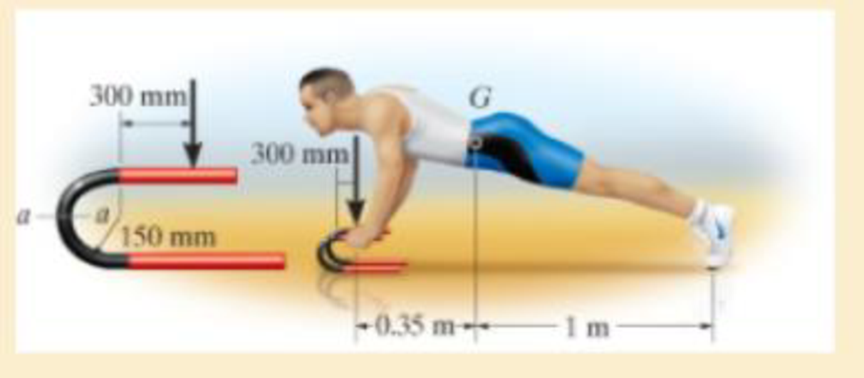
Chapter 8.2, Problem 46P
He is supported uniformly by two bars, each having a diameter of 25 mm. Assume the floor is smooth. Use the curved-beam formula to calculate the bending stress.
Expert Solution & Answer
Want to see the full answer?
Check out a sample textbook solution
Students have asked these similar questions
The axle of the freight train is subjected to loadings as shown below. The diameter of the axle is 137.5 mm.
If it is supported by two journal bearings at C and D, determine the maximum bending Stress. Include a FBD, SFD and BMD using either the section or graphical method. Draw a cross-section of the shaft and indicate the points of maximum tension and compression.
The simply supported joist is used in the construction of a floor for a building. In order to keep the floor low with respect to the sill beams C and D, the ends of the joists are notched as shown. If the allowable shear stress is tallow = 350 psi and the allowable bending stress is sallow = 1500 psi, determine the height h that will cause the beam to reach both allowable stresses at the same time. Also, what load P causes this to happen? Neglect the stressconcentration at the notch.
Solve for Internal Normal Force, Shear Force and Bending Moment at point C and D. where Roll no=11
Chapter 8 Solutions
STANDALONE CODE MECHANICS OF MATERIALS-M
Ch. 8.1 - If it is subjected to an internal pressure of p =...Ch. 8.1 - If it is subjected to an internal pressure of p =...Ch. 8.1 - The thin-walled cylinder can be supported in one...Ch. 8.1 - If the inner diameter of the tank is 22 in., and...Ch. 8.1 - Prob. 5PCh. 8.1 - 88. The steel water pipe has an inner diameter of...Ch. 8.1 - The steel water pipe has an inner diameter of 12...Ch. 8.2 - Fundamental Problems F81. Determine the normal...Ch. 8.2 - Show the results in a differential element at the...Ch. 8.2 - Determine the state of stress at point A on the...
Ch. 8.2 - Determine the magnitude of the load P that will...Ch. 8.2 - Determine the state of stress at point B. Show the...Ch. 8.2 - Determine the state of stress at point A on the...Ch. 8.2 - Determine the state of stress at point A on the...Ch. 8.2 - Show the results in a differential element at the...Ch. 8.2 - The plate has a thickness of 20 mm and P acts...Ch. 8.2 - Plot the distribution of normal stress acting...Ch. 8.2 - Also, plot the normal-stress distribution over the...Ch. 8.2 - Determine the stress components at point A on the...Ch. 8.2 - Determine the stress components at point B on the...Ch. 8.2 - If it is subjected to the force system shown,...Ch. 8.2 - Neglect the weight of the block.Ch. 8.2 - Neglect the weight of the block.Ch. 8.2 - He is supported uniformly by two bars, each having...Ch. 8.2 - Specify the region to which this load can be...Ch. 8.2 - The pins at C and D are at the same location as...Ch. 8.2 - If the force at the ram on the clamp at D is P= 8...Ch. 8.2 - Determine the maximum ram force P that can be...Ch. 8.2 - and an outer radius of 3.00 in. If the face of the...Ch. 8 - If it supports a cable loading of 800 lb,...Ch. 8 - Determine the state of stress at point E on the...Ch. 8 - Determine the state of stress at point F on the...Ch. 8 - The suspender arm AE has a square cross-sectional...Ch. 8 - If the cross section of the femur at section aa...Ch. 8 - If it has a mass of 5 kg/m, determine the largest...Ch. 8 - and is used to support the vertical reactions of...Ch. 8 - and is used to support the vertical reactions of...
Knowledge Booster


Learn more about
Need a deep-dive on the concept behind this application? Look no further. Learn more about this topic, mechanical-engineering and related others by exploring similar questions and additional content below.Similar questions
- A laminated spring Im long is built in 100 mm x 10 mm plates. If the spring is to carry a load of 10 kN at its centre, determine the number of plates required for the spring. Take allowable bending stress as 150 MPa.arrow_forwardThe beam is supported by a pin at point A and a roller at kN point B. A distributed load of W₁ = 8 - and an applied m force of F₁ = 12 kN are applied to the beam. The beam has an allowable bending stress of allow = 6 MPa. Neglect the weight and thickness of the beam. Take the origin for all functions to be at A., i.e. start at the left and go right. Must use positive sign convention for V and M. d3 1 d3 d1 W1 d1 B O h d2 F₁ Values for the figure are given in the following table. Note the figure may not be to scale. Dimensions for the whole beam Variable Value d₁ 4 m d₂ 2 marrow_forwardDetermine the reaction forces R1 and R2 and show the shear and bending moment diagram. Data: Point load (left-most) = 90.126 N Uniformly distributed load (80mm to 260mm) = 0.14444 N/mm Uniformly distributed load (160mm to 180mm) = 6.5 N/mmarrow_forward
- The bending moment M is applied to the box beam in the x-y plane at the orientation show below. (a) Determine the maximum magnitude of the bending moment M so that the tensile bending stress in the member does not exceed 15 ksi. (b) Determine the angle that the neutral axis makes with the y-axis. (c) The position or positions on the beam where the maximum compressive bending stress occurs given your answer in a. Clearly indicate this on the figure below (also calculate the values) 4 in. B 4 in. M 6 in. 6 in.arrow_forwardGiven the figure, find the maximum bending stress. Indicate ifcompression or tension. Given: M = 45 kN-m; a = 100 mm; b = 15 mm; c = 116 mm; d = 18 mm.arrow_forwardThe eye hook has the dimensions shown. If it supports a cable loading of 800 lb, determine the maximum normal stress at section a–a and sketch the stress distribution acting over the cross section. Use the curved-beam formula to calculate the bending stress.arrow_forward
- Divide the plane frame structure shown in the image into suitable parts for analytical examination and draw the free-body diagrams of the parts. Additionally, determine the shear force and bending moment diagrams of the structure. F = 10 kN and a = 2 m. There is a roller support on the left edge and a fixed support at the bottom.arrow_forwardThe simply supported joist is used in the construction of a floor for a building. In order to keep the floor low with respect to the sill beams C and D, the ends of the joist are notched as shown. If the allowable shear stress is tallow = 350 psi and the allowable bending stress is s allow = 1700 psi, determine the smallest height h so that the beam will support a load of P = 600 lb. Also, will the entire joist safely support the load? Neglect the stress concentration at the notch.arrow_forwardThe beam is constructed of four boards, and is subjected to a moment of M=200 kip in, calculate the resultant force on the top board C. -1 in. 1 in. M-200 kip.in 13 in 80 T in. 8 in 1 in.arrow_forward
- Construct the shear force and bending moment diagram with the help of free body diagrams (value of Y=7)arrow_forwardA box is produced by joining the wooden and plywood rectangular elements with screws as shown in the section. The shear force that each screw used in the cross section joint can safely carry is V = 2 kN. If the beam element created in this way is loaded from the middle of the span with a load of P = 100 kN, find the screw gap a and the total number of screws to be used in the beam element. (Cross-section dimensions t = 15mm, b = 150mm, c = 30mm, h = 180mm; beam support span L = 5m)arrow_forwardThe handle of the press is subjected to a force of 20 lb. Due to internal gearing, this causes the block to be subjected to a compressive force of 80 lb. Determine the normal-stress acting in the frame at points along the outside flanges A and B. Use the curved-beam formula to calculate the bending stress.arrow_forward
arrow_back_ios
SEE MORE QUESTIONS
arrow_forward_ios
Recommended textbooks for you
 Mechanics of Materials (MindTap Course List)Mechanical EngineeringISBN:9781337093347Author:Barry J. Goodno, James M. GerePublisher:Cengage Learning
Mechanics of Materials (MindTap Course List)
Mechanical Engineering
ISBN:9781337093347
Author:Barry J. Goodno, James M. Gere
Publisher:Cengage Learning
Everything About COMBINED LOADING in 10 Minutes! Mechanics of Materials; Author: Less Boring Lectures;https://www.youtube.com/watch?v=N-PlI900hSg;License: Standard youtube license