
STANDALONE CODE MECHANICS OF MATERIALS-M
11th Edition
ISBN: 9780137605200
Author: HIBBELER
Publisher: PEARSON
expand_more
expand_more
format_list_bulleted
Concept explainers
Videos
Textbook Question
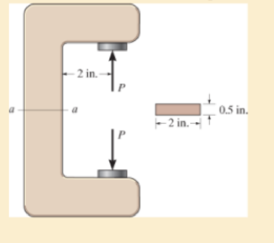
Chapter 8.2, Problem 4FP
Determine the magnitude of the load P that will cause a maximum normal stress of σmax = 30 ksi in the link along section a–a.
F8–4
Expert Solution & Answer

Trending nowThis is a popular solution!

Students have asked these similar questions
The bell-crank mechanism is in equilibrium for an applied load of F1 = 11 kN applied at A. Assume a = 250mm, b = 100mm, c = 90mm, and θ = 40°. Pin B is in a double-shear connection and has a diameter of 29 mm. The bell crank has a thickness of 31 mm. Determine the shear stress in pin B. Express your answer in MPa rounded to the nearest hundredths.
The bell-crank mechanism is in equilibrium for an applied load of F1 = 11 kN applied at A. Assume a = 250mm, b = 100mm, c = 90mm, and θ = 40°. Pin B is in a double-shear connection and has a diameter of 29 mm. The bell crank has a thickness of 31 mm. Determine the shear stress in pin B. and the the bearing stress in the bell crank at B.
The five-bolt connection must support an applied load of P = 3800 lb. If the average shear stress in the bolts must be limited to 34 ksi,
determine the minimum bolt diameter that may be used for this connection.
Answer: dmin =
i
in.
Chapter 8 Solutions
STANDALONE CODE MECHANICS OF MATERIALS-M
Ch. 8.1 - If it is subjected to an internal pressure of p =...Ch. 8.1 - If it is subjected to an internal pressure of p =...Ch. 8.1 - The thin-walled cylinder can be supported in one...Ch. 8.1 - If the inner diameter of the tank is 22 in., and...Ch. 8.1 - Prob. 5PCh. 8.1 - 88. The steel water pipe has an inner diameter of...Ch. 8.1 - The steel water pipe has an inner diameter of 12...Ch. 8.2 - Fundamental Problems F81. Determine the normal...Ch. 8.2 - Show the results in a differential element at the...Ch. 8.2 - Determine the state of stress at point A on the...
Ch. 8.2 - Determine the magnitude of the load P that will...Ch. 8.2 - Determine the state of stress at point B. Show the...Ch. 8.2 - Determine the state of stress at point A on the...Ch. 8.2 - Determine the state of stress at point A on the...Ch. 8.2 - Show the results in a differential element at the...Ch. 8.2 - The plate has a thickness of 20 mm and P acts...Ch. 8.2 - Plot the distribution of normal stress acting...Ch. 8.2 - Also, plot the normal-stress distribution over the...Ch. 8.2 - Determine the stress components at point A on the...Ch. 8.2 - Determine the stress components at point B on the...Ch. 8.2 - If it is subjected to the force system shown,...Ch. 8.2 - Neglect the weight of the block.Ch. 8.2 - Neglect the weight of the block.Ch. 8.2 - He is supported uniformly by two bars, each having...Ch. 8.2 - Specify the region to which this load can be...Ch. 8.2 - The pins at C and D are at the same location as...Ch. 8.2 - If the force at the ram on the clamp at D is P= 8...Ch. 8.2 - Determine the maximum ram force P that can be...Ch. 8.2 - and an outer radius of 3.00 in. If the face of the...Ch. 8 - If it supports a cable loading of 800 lb,...Ch. 8 - Determine the state of stress at point E on the...Ch. 8 - Determine the state of stress at point F on the...Ch. 8 - The suspender arm AE has a square cross-sectional...Ch. 8 - If the cross section of the femur at section aa...Ch. 8 - If it has a mass of 5 kg/m, determine the largest...Ch. 8 - and is used to support the vertical reactions of...Ch. 8 - and is used to support the vertical reactions of...
Knowledge Booster


Learn more about
Need a deep-dive on the concept behind this application? Look no further. Learn more about this topic, mechanical-engineering and related others by exploring similar questions and additional content below.Similar questions
- F13-4. Determine the magnitude of the load P that will cause a maximum normal stress of nus = 210 MPa in the link along section a-a. Omm 12 mm S0 mmarrow_forwardThe five-bolt connection must support an applied load of P = 3900 lb. If the average shear stress in the bolts must be limited to 25 ksi, determine the minimum bolt diameter that may be used for this connection.arrow_forwardAnswer the ff. The bell-crank mechanism is in equilibrium for an applied load of F1 = 19 kN applied at A. Assume a = 330mm, b = 160mm, c = 75mm, and θ = 35°. Pin B is in a double-shear connection and has a diameter of 24 mm. The bell crank has a thickness of 28 mm. Determine(a) the shear stress in pin B.(b) the bearing stress in the bell crank at B.arrow_forward
- The five-bolt connection must support an applied load of P = 2600 Ib. If the average shear stress in the bolts must be limited to 27 ksi, determine the minimum bolt diameter that may be used for this connection. Answer:dmin = in.arrow_forwardA 2" diameter pin connects the three links as shown. The links have a 3" by 3" cross- section. Determine the shear stress in the pin and the maximum normal stress in the upper link. If the material is 6061 Aluminum (gy = 35 ksi, y= 20 ksi) determine the factor of safety for both the pin and the link. 9000 (1bf)arrow_forwardThe d = 13-mm-diameter solid rod passes through a D = 20-mm-diameter hole in the support plate. When a load Pis applied to the rod, the rod head rests on the support plate. The support plate has a thickness of b = 15 mm. The rod head has a diameter of a = 31 mm, and the head has a thickness of t= 10 mm. If the normal stress produced in the rod by load Pis 150 MPa, determine (a) the bearing stress acting between the support plate and the rod head. (b) the average shear stress produced in the rod head. (c) the punching shear stress produced in the support plate by the rod head. Support Plate - Hole diameter D P Rod Нead a Calculate the cross-sectional area of the rod. Answer: Arod = i mm2arrow_forward
- The hanger is supported using a rectangular pin. Determine the magnitude of the allowable suspended load P if the allowable bearing stress is (σb)allow=220 MPa, the allowable tensile stress is (σt)allow=150 MPa, and the allowable shear stress is τallow=130 MPa. Take t=6 mm, a=5 mm, and b=25 mm. draw free-body diagramarrow_forwardThe bell-crank mechanism is in equilibrium for an applied load of F₁ = 20 kN applied at A. Assume a = 270mm, b = 170mm, c = 70mm, and 9 = 50°. Pin B is in a double-shear connection and has a diameter of 24 mm. The bell crank has a thickness of 36 mm. Determine the bearing stress in the bell crank at B. Answer in MPa rounded-off to 2 decimal places. F₁ Bell crank Support bracket Add your answer B b 4arrow_forwardThe tension member is fastened together using two bolts, one on each side of the member as shown. Each bolt has a diameter of 0.3 in. Determine the maximum load P that can be applied to the member if the allowable shear stress for the bolts is tlow = 12 ksi allow and the allowable average normal stress is o, = 20 ksi. allow 60°arrow_forward
- The beam is supported by a pin at Ċ and by a short link AB. Each pin has a diameter of 12 mm. Assume L = 1.2 m and 9 = 35°. If the average shear stress in the pins at A, B, and C cannot exceed 125 MPa, determine the maximum distributed load Wmax that can be supported by the structure. A e Answer: Wmax i B W L kN/marrow_forwardThe d = 15-mm-diameter solid rod passes through a D = 20-mm-diameter hole in the support plate. When a load P is applied to the rod, the rod head rests on the support plate. The support plate has a thickness of b = 15 mm. The rod head has a diameter of a = 30 mm, and the head has a thickness of t = 9 mm. If the normal stress produced in the rod by load P is 200 MPa, determine (a) the bearing stress acting between the support plate and the rod head. (b) the average shear stress produced in the rod head. (c) the punching shear stress produced in the support plate by the rod head. Support Plate Hole diameter D Rod Head Calculate the cross-sectional area of the rod. Answer: Arodi mm²arrow_forwardThe d = 13-mm-diameter solid rod passes through a D=21-mm-diameter hole in the support plate. When a load P is applied to the rod, the rod head rests on the support plate. The support plate has a thickness of b = 12 mm. The rod head has a diameter of a = 28 mm, and the head has a thickness of t = 8 mm. If the normal stress produced in the rod by load P is 150 MPa, determine (a) the bearing stress acting between the support plate and the rod head. (b) the average shear stress produced in the rod head. (c) the punching shear stress produced in the support plate by the rod head. Support Plate Hole diameter D Rod Head b Calculate the cross-sectional area of the rod. Answer: Arod mm²arrow_forward
arrow_back_ios
SEE MORE QUESTIONS
arrow_forward_ios
Recommended textbooks for you
 Elements Of ElectromagneticsMechanical EngineeringISBN:9780190698614Author:Sadiku, Matthew N. O.Publisher:Oxford University Press
 Mechanics of Materials (10th Edition)Mechanical EngineeringISBN:9780134319650Author:Russell C. HibbelerPublisher:PEARSON
 Thermodynamics: An Engineering ApproachMechanical EngineeringISBN:9781259822674Author:Yunus A. Cengel Dr., Michael A. BolesPublisher:McGraw-Hill Education
 Control Systems EngineeringMechanical EngineeringISBN:9781118170519Author:Norman S. NisePublisher:WILEY
 Mechanics of Materials (MindTap Course List)Mechanical EngineeringISBN:9781337093347Author:Barry J. Goodno, James M. GerePublisher:Cengage Learning
 Engineering Mechanics: StaticsMechanical EngineeringISBN:9781118807330Author:James L. Meriam, L. G. Kraige, J. N. BoltonPublisher:WILEY
Elements Of Electromagnetics
Mechanical Engineering
ISBN:9780190698614
Author:Sadiku, Matthew N. O.
Publisher:Oxford University Press
Mechanics of Materials (10th Edition)
Mechanical Engineering
ISBN:9780134319650
Author:Russell C. Hibbeler
Publisher:PEARSON
Thermodynamics: An Engineering Approach
Mechanical Engineering
ISBN:9781259822674
Author:Yunus A. Cengel Dr., Michael A. Boles
Publisher:McGraw-Hill Education
Control Systems Engineering
Mechanical Engineering
ISBN:9781118170519
Author:Norman S. Nise
Publisher:WILEY
Mechanics of Materials (MindTap Course List)
Mechanical Engineering
ISBN:9781337093347
Author:Barry J. Goodno, James M. Gere
Publisher:Cengage Learning
Engineering Mechanics: Statics
Mechanical Engineering
ISBN:9781118807330
Author:James L. Meriam, L. G. Kraige, J. N. Bolton
Publisher:WILEY
Mechanical Design (Machine Design) Clutches, Brakes and Flywheels Intro (S20 ME470 Class 15); Author: Professor Ted Diehl;https://www.youtube.com/watch?v=eMvbePrsT34;License: Standard Youtube License