Mechanics of Materials, Student Value Edition Plus Mastering Engineering with Pearson eText -- Access Card Package (10th Edition)
10th Edition
ISBN: 9780134326054
Author: Russell C. Hibbeler
Publisher: PEARSON
expand_more
expand_more
format_list_bulleted
Concept explainers
Videos
Textbook Question
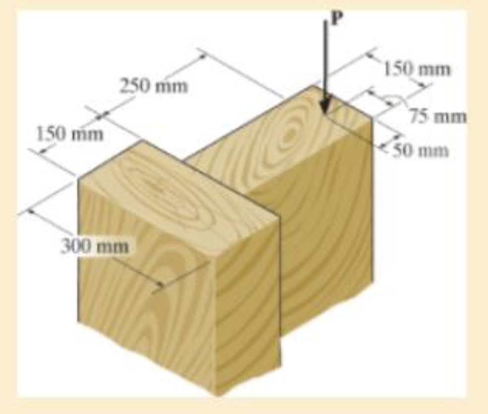
Chapter 8.2, Problem 8.25P
If the wood has an allowable normal stress of σallow = 6 MPa, determine the maximum allowable eccentric force P that can be applied to the column.
Expert Solution & Answer
Want to see the full answer?
Check out a sample textbook solution
Students have asked these similar questions
The supporting wheel on a scaffold is held in place on the leg using a 4-mm-diameter pin. If the wheel is subjected to a normal force of 3 kN, determine the average shear stress in the pin. Assume the pin only supports the vertical 3-kN load.
Determine the maximum axial force P that can be applied to the bar. The bar is made from steel and has an allowable stress of σallow = 147 MPa.
The plastic block is subjected to an axial compressive force of 600 N. Assuming that the caps at the top and bottom distribute the load uniformly throughout the block, determine the average normal and average shear stress acting along section a–a.
Chapter 8 Solutions
Mechanics of Materials, Student Value Edition Plus Mastering Engineering with Pearson eText -- Access Card Package (10th Edition)
Ch. 8.1 - If it is subjected to an internal pressure of p =...Ch. 8.1 - If it is subjected to an internal pressure of p =...Ch. 8.1 - The thin-walled cylinder can be supported in one...Ch. 8.1 - If the inner diameter of the tank is 22 in., and...Ch. 8.1 - Air pressure in the cylinder is increased by...Ch. 8.1 - Determine the maximum force P that can be exerted...Ch. 8.1 - A boiler is constructed of 8-mm-thick steel plates...Ch. 8.1 - 88. The steel water pipe has an inner diameter of...Ch. 8.1 - The steel water pipe has an inner diameter of 12...Ch. 8.1 - The A-36-steel band is 2 in. wide and is secured...
Ch. 8.1 - The gas pipe line is supported every 20 ft by...Ch. 8.1 - A pressure-vessel head is fabricated by welding...Ch. 8.1 - An A-36-steel hoop has an inner diameter of 23.99...Ch. 8.1 - The ring, having the dimensions shown, is placed...Ch. 8.1 - The inner ring A has an inner radius r1 and outer...Ch. 8.1 - Two hemispheres having an inner radius of 2 ft and...Ch. 8.1 - In order to increase the strength of the pressure...Ch. 8.2 - Show the results on the left segment.Ch. 8.2 - Show the stress that each of these loads produce...Ch. 8.2 - Fundamental Problems F81. Determine the normal...Ch. 8.2 - Show the results in a differential element at the...Ch. 8.2 - Determine the state of stress at point A on the...Ch. 8.2 - Determine the magnitude of the load P that will...Ch. 8.2 - Determine the state of stress at point B. Show the...Ch. 8.2 - Determine the state of stress at point A on the...Ch. 8.2 - Determine the state of stress at point A on the...Ch. 8.2 - Show the results in a differential element at the...Ch. 8.2 - Determine the shortest distance d to the edge of...Ch. 8.2 - The plate has a thickness of 20 mm and P acts...Ch. 8.2 - Plot the distribution of normal stress acting...Ch. 8.2 - Also, plot the normal-stress distribution over the...Ch. 8.2 - If the allowable normal stress for the steel is...Ch. 8.2 - If the applied force P = 1.50 kip, determine the...Ch. 8.2 - Determine the maximum normal stress on the cross...Ch. 8.2 - If the wood has an allowable normal stress of...Ch. 8.2 - Determine the maximum normal stress along section...Ch. 8.2 - Sketch the stress distribution along section aa of...Ch. 8.2 - Sketch the normal-stress distribution acting over...Ch. 8.2 - Determine the state of stress at points A and B,...Ch. 8.2 - If the force of 100 N is applied to the handles,...Ch. 8.2 - Determine the stress components at point A on the...Ch. 8.2 - Determine the stress components at point B on the...Ch. 8.2 - Determine the normal stress developed at points A...Ch. 8.2 - Sketch the normal-stress distribution acting over...Ch. 8.2 - Determine the state of stress at points A and B,...Ch. 8.2 - Determine the state of stress at point A on the...Ch. 8.2 - Determine the state of stress at point B on the...Ch. 8.2 - Determine the state of stress acting at point D....Ch. 8.2 - Determine the state of stress acting at point E....Ch. 8.2 - If it is subjected to the force system shown,...Ch. 8.2 - Solve Prob.840 for point B.Ch. 8.2 - Determine the stress components acting on the...Ch. 8.2 - Determine the stress components acting on the...Ch. 8.2 - Neglect the weight of the block.Ch. 8.2 - Neglect the weight of the block.Ch. 8.2 - He is supported uniformly by two bars, each having...Ch. 8.2 - Determine the state of stress at point A, and show...Ch. 8.2 - Determine the state of stress at point B, and show...Ch. 8.2 - Determine the state of stress at point C, and show...Ch. 8.2 - Determine the maximum radius e at which the load P...Ch. 8.2 - Specify the region to which this load can be...Ch. 8.2 - Determine the smallest force P that can be applied...Ch. 8.2 - The coiled spring is subjected to a force P. If we...Ch. 8.2 - The pins at C and D are at the same location as...Ch. 8.2 - Determine the state of stress at point A, and show...Ch. 8.2 - Determine the state of stress at point B, and show...Ch. 8.2 - Determine the stress components at points A and B...Ch. 8.2 - Determine the stress components at points C and D...Ch. 8.2 - Determine the stress components in the support...Ch. 8.2 - Determine the stress components in the support...Ch. 8.2 - If the force at the ram on the clamp at D is P= 8...Ch. 8.2 - Determine the maximum ram force P that can be...Ch. 8.2 - and an outer radius of 3.00 in. If the face of the...Ch. 8.2 - for points E and F.Ch. 8.2 - Determine the stress components at points A and B...Ch. 8.2 - Solve Prob.8-65 for points C and D.Ch. 8.2 - Due to internal gearing, this causes the block to...Ch. 8.2 - Determine the state of stress at point A and show...Ch. 8.2 - Solve Prob.868 for point B.Ch. 8.2 - Determine the stress components at point A. Sketch...Ch. 8.2 - for the stress components at point B.Ch. 8.2 - Determine the state of stress at point A at...Ch. 8.2 - Determine the state of stress at point B at...Ch. 8 - If it supports a cable loading of 800 lb,...Ch. 8 - Determine the state of stress at point E on the...Ch. 8 - Determine the state of stress at point F on the...Ch. 8 - The suspender arm AE has a square cross-sectional...Ch. 8 - If the cross section of the femur at section aa...Ch. 8 - If it has a mass of 5 kg/m, determine the largest...Ch. 8 - and is used to support the vertical reactions of...Ch. 8 - and is used to support the vertical reactions of...
Knowledge Booster


Learn more about
Need a deep-dive on the concept behind this application? Look no further. Learn more about this topic, mechanical-engineering and related others by exploring similar questions and additional content below.Similar questions
- The column is constructed from high-strength concrete and eight A992 steel reinforcing rods. If the column is subjected to an axial force of 200 kip, determine the average normal stress in the concrete and in each rod. Eachrod has a diameter of 1 in.arrow_forwardThe hydraulic cylindere has an innner diameter of 100 mm and wall thickness of t= 4mm. If it is made from a material having an allowable normal stress of sigma allow= 146.0 MPa, determine the maximum allowable force P.arrow_forwardThe pier is made of a material having a specific weight g. If it has a square cross-section, determine its width w as a function of z so that the average normal stress in the pier remains constant. The pier supports a constant load P at its top where its width is w1.arrow_forward
- If the average normal stress in each of the 20-mm-diameter bars is not allowed to exceed 150 MPa, determine the maximum force P that can be applied to joint C.arrow_forwardDetermine the allowable weight that the assembly can handle if the cable AB has a working stress of 200 Mpa and cable AC has a working stress of 150 Mpa. The cable cross sectional areas are 300 mm2for cable AB and 330 mm2for cable AC.arrow_forwardThe lever is attached to the shaft A using a key that has a width d and length of 25 mm. If the shaft is fixed and a vertical force of 200 N is applied perpendicular to the handle, determine the dimension d if the allowable shear stress for the key is tallow = 35 MPa.arrow_forward
- The bolt has a diameter of 20 (mm) and passes through a tube that has an inner diameter of 50 (mm) and an outer diameter of 60 (mm). If the bolt and tube are made of A-36 steel, determine the normal stress in the tube and bolt when a force of 40 (kN) is applied to the bolt. Assume the end caps are rigid.arrow_forwardThe strut is glued to the horizontal member at surface AB. If the strut has a thickness of 25 mm and the glue can withstand an average shear stress of 600 kPa, determine the maximum force P that can be applied to the strut.arrow_forwardThe yoke-and-rod connection is subjected to a tensile force of 5 kN. Determine the average normal stress in each rod and the average shear stress in the pin A between the members.arrow_forward
- The spreader bar is used to lift the 2000-lb tank. Determine the state of stress at points A and B, and indicate the results on a differential volume element.arrow_forwardThe tension member is fastened together using two bolts, one on each side of the member as shown. Each bolt has a diameter of 0.3 in. Determine the maximum load P that can be applied to the member if the allowable shearstress for the bolts is tallow = 12 ksi and the allowable average normal stress is sallow = 20 ksi.arrow_forwardThe short concrete cylinder having a diameter of 50 mm is subjected to a torque of 500 N # m and an axial compressive force of 2 kN. Determine if it fails according to the maximum normal stress theory. The ultimate stress of the concrete is sult = 28 MPa.arrow_forward
arrow_back_ios
SEE MORE QUESTIONS
arrow_forward_ios
Recommended textbooks for you
 Elements Of ElectromagneticsMechanical EngineeringISBN:9780190698614Author:Sadiku, Matthew N. O.Publisher:Oxford University Press
 Mechanics of Materials (10th Edition)Mechanical EngineeringISBN:9780134319650Author:Russell C. HibbelerPublisher:PEARSON
 Thermodynamics: An Engineering ApproachMechanical EngineeringISBN:9781259822674Author:Yunus A. Cengel Dr., Michael A. BolesPublisher:McGraw-Hill Education
 Control Systems EngineeringMechanical EngineeringISBN:9781118170519Author:Norman S. NisePublisher:WILEY
 Mechanics of Materials (MindTap Course List)Mechanical EngineeringISBN:9781337093347Author:Barry J. Goodno, James M. GerePublisher:Cengage Learning
 Engineering Mechanics: StaticsMechanical EngineeringISBN:9781118807330Author:James L. Meriam, L. G. Kraige, J. N. BoltonPublisher:WILEY
Elements Of Electromagnetics
Mechanical Engineering
ISBN:9780190698614
Author:Sadiku, Matthew N. O.
Publisher:Oxford University Press
Mechanics of Materials (10th Edition)
Mechanical Engineering
ISBN:9780134319650
Author:Russell C. Hibbeler
Publisher:PEARSON
Thermodynamics: An Engineering Approach
Mechanical Engineering
ISBN:9781259822674
Author:Yunus A. Cengel Dr., Michael A. Boles
Publisher:McGraw-Hill Education
Control Systems Engineering
Mechanical Engineering
ISBN:9781118170519
Author:Norman S. Nise
Publisher:WILEY
Mechanics of Materials (MindTap Course List)
Mechanical Engineering
ISBN:9781337093347
Author:Barry J. Goodno, James M. Gere
Publisher:Cengage Learning
Engineering Mechanics: Statics
Mechanical Engineering
ISBN:9781118807330
Author:James L. Meriam, L. G. Kraige, J. N. Bolton
Publisher:WILEY
Everything About COMBINED LOADING in 10 Minutes! Mechanics of Materials; Author: Less Boring Lectures;https://www.youtube.com/watch?v=N-PlI900hSg;License: Standard youtube license