
MECHANICS OF MATERIALS (LOOSE)-W/ACCESS
10th Edition
ISBN: 9780134583228
Author: HIBBELER
Publisher: PEARSON
expand_more
expand_more
format_list_bulleted
Concept explainers
Videos
Textbook Question
Chapter 8.2, Problem 8.4FP
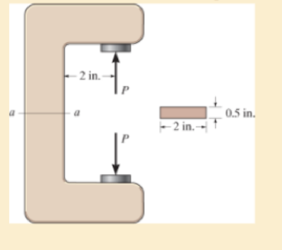
Determine the magnitude of the load P that will cause a maximum normal stress of σmax = 30 ksi in the link along section a–a.
F8–4
Expert Solution & Answer

Trending nowThis is a popular solution!

Students have asked these similar questions
If the bolt head and the supporting bracket are made of the same material having a failure shear stress of tfail = 120 MPa, determine the maximum allowable force P that can be applied to the bolt so that it does not pullthrough the plate. Apply a factor of safety of F.S. = 2.5 against shear failure.
The five-bolt connection must support an applied load of P = 3900 lb. If the average shear stress in the bolts must be limited to 25 ksi, determine the minimum bolt diameter that may be used for this connection.
The 6061-T6 aluminum bar has a square cross section of 25 mm by 25 mm. If it is 2 m long, determine the maximum shear stress in the bar and the rotation of one end relative to the other end.
Chapter 8 Solutions
MECHANICS OF MATERIALS (LOOSE)-W/ACCESS
Ch. 8.1 - If it is subjected to an internal pressure of p =...Ch. 8.1 - If it is subjected to an internal pressure of p =...Ch. 8.1 - The thin-walled cylinder can be supported in one...Ch. 8.1 - If the inner diameter of the tank is 22 in., and...Ch. 8.1 - Air pressure in the cylinder is increased by...Ch. 8.1 - Determine the maximum force P that can be exerted...Ch. 8.1 - A boiler is constructed of 8-mm-thick steel plates...Ch. 8.1 - 88. The steel water pipe has an inner diameter of...Ch. 8.1 - The steel water pipe has an inner diameter of 12...Ch. 8.1 - The A-36-steel band is 2 in. wide and is secured...
Ch. 8.1 - The gas pipe line is supported every 20 ft by...Ch. 8.1 - A pressure-vessel head is fabricated by welding...Ch. 8.1 - An A-36-steel hoop has an inner diameter of 23.99...Ch. 8.1 - The ring, having the dimensions shown, is placed...Ch. 8.1 - The inner ring A has an inner radius r1 and outer...Ch. 8.1 - Two hemispheres having an inner radius of 2 ft and...Ch. 8.1 - In order to increase the strength of the pressure...Ch. 8.2 - Show the results on the left segment.Ch. 8.2 - Show the stress that each of these loads produce...Ch. 8.2 - Fundamental Problems F81. Determine the normal...Ch. 8.2 - Show the results in a differential element at the...Ch. 8.2 - Determine the state of stress at point A on the...Ch. 8.2 - Determine the magnitude of the load P that will...Ch. 8.2 - Determine the state of stress at point B. Show the...Ch. 8.2 - Determine the state of stress at point A on the...Ch. 8.2 - Determine the state of stress at point A on the...Ch. 8.2 - Show the results in a differential element at the...Ch. 8.2 - Determine the shortest distance d to the edge of...Ch. 8.2 - The plate has a thickness of 20 mm and P acts...Ch. 8.2 - Plot the distribution of normal stress acting...Ch. 8.2 - Also, plot the normal-stress distribution over the...Ch. 8.2 - If the allowable normal stress for the steel is...Ch. 8.2 - If the applied force P = 1.50 kip, determine the...Ch. 8.2 - Determine the maximum normal stress on the cross...Ch. 8.2 - If the wood has an allowable normal stress of...Ch. 8.2 - Determine the maximum normal stress along section...Ch. 8.2 - Sketch the stress distribution along section aa of...Ch. 8.2 - Sketch the normal-stress distribution acting over...Ch. 8.2 - Determine the state of stress at points A and B,...Ch. 8.2 - If the force of 100 N is applied to the handles,...Ch. 8.2 - Determine the stress components at point A on the...Ch. 8.2 - Determine the stress components at point B on the...Ch. 8.2 - Determine the normal stress developed at points A...Ch. 8.2 - Sketch the normal-stress distribution acting over...Ch. 8.2 - Determine the state of stress at points A and B,...Ch. 8.2 - Determine the state of stress at point A on the...Ch. 8.2 - Determine the state of stress at point B on the...Ch. 8.2 - Determine the state of stress acting at point D....Ch. 8.2 - Determine the state of stress acting at point E....Ch. 8.2 - If it is subjected to the force system shown,...Ch. 8.2 - Solve Prob.840 for point B.Ch. 8.2 - Determine the stress components acting on the...Ch. 8.2 - Determine the stress components acting on the...Ch. 8.2 - Neglect the weight of the block.Ch. 8.2 - Neglect the weight of the block.Ch. 8.2 - He is supported uniformly by two bars, each having...Ch. 8.2 - Determine the state of stress at point A, and show...Ch. 8.2 - Determine the state of stress at point B, and show...Ch. 8.2 - Determine the state of stress at point C, and show...Ch. 8.2 - Determine the maximum radius e at which the load P...Ch. 8.2 - Specify the region to which this load can be...Ch. 8.2 - Determine the smallest force P that can be applied...Ch. 8.2 - The coiled spring is subjected to a force P. If we...Ch. 8.2 - The pins at C and D are at the same location as...Ch. 8.2 - Determine the state of stress at point A, and show...Ch. 8.2 - Determine the state of stress at point B, and show...Ch. 8.2 - Determine the stress components at points A and B...Ch. 8.2 - Determine the stress components at points C and D...Ch. 8.2 - Determine the stress components in the support...Ch. 8.2 - Determine the stress components in the support...Ch. 8.2 - If the force at the ram on the clamp at D is P= 8...Ch. 8.2 - Determine the maximum ram force P that can be...Ch. 8.2 - and an outer radius of 3.00 in. If the face of the...Ch. 8.2 - for points E and F.Ch. 8.2 - Determine the stress components at points A and B...Ch. 8.2 - Solve Prob.8-65 for points C and D.Ch. 8.2 - Due to internal gearing, this causes the block to...Ch. 8.2 - Determine the state of stress at point A and show...Ch. 8.2 - Solve Prob.868 for point B.Ch. 8.2 - Determine the stress components at point A. Sketch...Ch. 8.2 - for the stress components at point B.Ch. 8.2 - Determine the state of stress at point A at...Ch. 8.2 - Determine the state of stress at point B at...Ch. 8 - If it supports a cable loading of 800 lb,...Ch. 8 - Determine the state of stress at point E on the...Ch. 8 - Determine the state of stress at point F on the...Ch. 8 - The suspender arm AE has a square cross-sectional...Ch. 8 - If the cross section of the femur at section aa...Ch. 8 - If it has a mass of 5 kg/m, determine the largest...Ch. 8 - and is used to support the vertical reactions of...Ch. 8 - and is used to support the vertical reactions of...
Knowledge Booster


Learn more about
Need a deep-dive on the concept behind this application? Look no further. Learn more about this topic, mechanical-engineering and related others by exploring similar questions and additional content below.Similar questions
- The bolt has a diameter of 20 (mm) and passes through a tube that has an inner diameter of 50 (mm) and an outer diameter of 60 (mm). If the bolt and tube are made of A-36 steel, determine the normal stress in the tube and bolt when a force of 40 (kN) is applied to the bolt. Assume the end caps are rigid.arrow_forwardThe pins on the frame at B and C each have a diameter of 0.25 in. If those pins are subjected to double shear, determine the factor of safety of each pin if the allowable stress for each pin is 12 ksi.arrow_forwardThe bell-crank mechanism is in equilibrium for an applied load of F1 = 19 kN applied at A. Assume a = 270mm, b = 140mm, c = 75mm, and θ = 40°. Pin B is in a double-shear connection and has a diameter of 33 mm. The bell crank has a thickness of 39 mm. Determine(a) the shear stress in pin B.(b) the bearing stress in the bell crank at B.arrow_forward
- The connection is made using a bolt and nut and two washers. If the allowable bearing stress of the washers on the boards is (sb)allow = 2 ksi, and the allowable tensile stress within the bolt shank S is (st)allow = 18 ksi, determine the maximum allowable tension in the bolt shank. The bolt shankhas a diameter of 0.31 in., and the washers have an outer diameter of 0.75 in. and inner diameter (hole) of 0.50 in.arrow_forwardTwo A992 steel pipes, each having a cross-sectional area of 0.32 in2, are screwed together using a union at B. Originally the assembly is adjusted so that no load is on the pipe. If the union is then tightened so that its screw, having a lead of 0.15 in., undergoes two full turns, determine the average normal stress developed in the pipe. Assume that the union and couplings at A and C are rigid. Neglect the size of the union. Note: The lead would cause the pipe, when unloaded, to shorten 0.15 in. when the union is rotated one revolution.arrow_forwardThe aluminum bracket A is used to support the centrally applied load of 8 kip. If it has a thickness of 0.5 in., determine the smallest height h in order to prevent a shear failure. The failure shear stress is tfail = 23 ksi. Use a factorof safety for shear of F.S. = 2.5.arrow_forward
- The three suspender bars AB, CD, and EF are made of A-36 steel (E = 250 MPa) and have equal cross-sectional areas of 400 mm2. Determine the average normal stress in each bar if the rigid beam is subjected to a force of P = 80 kN. Let d = 3 m and L = 8 marrow_forwardThe two cylindrical rod segments are fixed to the rigid walls such that there is a gap of 0.01 in. between them when T1 = 60°F. Each rod has a diameter of 1.25 in. Determine the average normal stress in each rod if T2 = 400 F, and also calculate the new length of the aluminum segment. Take aal = 13(10-6)>°F, Eal = 10(103) ksi, (sY)al = 40 ksi, acu = 9.4(10-6)>°F, (sY)cu = 50 ksi, and Ecu = 15(103) ksiarrow_forwardThe bell-crank mechanism is in equilibrium for an applied load of F1 = 11 kN applied at A. Assume a = 250mm, b = 100mm, c = 90mm, and θ = 40°. Pin B is in a double-shear connection and has a diameter of 29 mm. The bell crank has a thickness of 31 mm. Determine the shear stress in pin B. and the the bearing stress in the bell crank at B.arrow_forward
- A 100-mm-long rod has a diameter of 15 mm. If an axial tensile load of 10 kN is applied to it, determine the change in its diameter. E = 70 GPa, n = 0.35.arrow_forwardThe A-36 steel bar consists of two segments, one of a circular cross-section of radius r, and one of square cross-section. If the bar is subjected to the axial loading of P, determine the dimensions of the square segment so that the strain energy within the square segment is the same as in the circular segment.arrow_forwardThe short concrete cylinder having a diameter of 50 mm is subjected to a torque of 500 N # m and an axial compressive force of 2 kN. Determine if it fails according to the maximum normal stress theory. The ultimate stress of the concrete is sult = 28 MPa.arrow_forward
arrow_back_ios
SEE MORE QUESTIONS
arrow_forward_ios
Recommended textbooks for you
 Elements Of ElectromagneticsMechanical EngineeringISBN:9780190698614Author:Sadiku, Matthew N. O.Publisher:Oxford University Press
 Mechanics of Materials (10th Edition)Mechanical EngineeringISBN:9780134319650Author:Russell C. HibbelerPublisher:PEARSON
 Thermodynamics: An Engineering ApproachMechanical EngineeringISBN:9781259822674Author:Yunus A. Cengel Dr., Michael A. BolesPublisher:McGraw-Hill Education
 Control Systems EngineeringMechanical EngineeringISBN:9781118170519Author:Norman S. NisePublisher:WILEY
 Mechanics of Materials (MindTap Course List)Mechanical EngineeringISBN:9781337093347Author:Barry J. Goodno, James M. GerePublisher:Cengage Learning
 Engineering Mechanics: StaticsMechanical EngineeringISBN:9781118807330Author:James L. Meriam, L. G. Kraige, J. N. BoltonPublisher:WILEY
Elements Of Electromagnetics
Mechanical Engineering
ISBN:9780190698614
Author:Sadiku, Matthew N. O.
Publisher:Oxford University Press
Mechanics of Materials (10th Edition)
Mechanical Engineering
ISBN:9780134319650
Author:Russell C. Hibbeler
Publisher:PEARSON
Thermodynamics: An Engineering Approach
Mechanical Engineering
ISBN:9781259822674
Author:Yunus A. Cengel Dr., Michael A. Boles
Publisher:McGraw-Hill Education
Control Systems Engineering
Mechanical Engineering
ISBN:9781118170519
Author:Norman S. Nise
Publisher:WILEY
Mechanics of Materials (MindTap Course List)
Mechanical Engineering
ISBN:9781337093347
Author:Barry J. Goodno, James M. Gere
Publisher:Cengage Learning
Engineering Mechanics: Statics
Mechanical Engineering
ISBN:9781118807330
Author:James L. Meriam, L. G. Kraige, J. N. Bolton
Publisher:WILEY
Mechanical Design (Machine Design) Clutches, Brakes and Flywheels Intro (S20 ME470 Class 15); Author: Professor Ted Diehl;https://www.youtube.com/watch?v=eMvbePrsT34;License: Standard Youtube License