
MECHANICS OF MATERIALS (LOOSE)-W/ACCESS
10th Edition
ISBN: 9780134583228
Author: HIBBELER
Publisher: PEARSON
expand_more
expand_more
format_list_bulleted
Concept explainers
Videos
Textbook Question
Chapter 8.1, Problem 8.13P
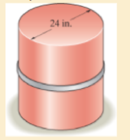
An A-36-steel hoop has an inner diameter of 23.99 in., thickness of 0.25 in., and width of 1 in. If it and the 24-in.-diameter rigid cylinder have a temperature of 65° F. determine the temperature to which the hoop should be heated in order for it to just slip over the cylinder. What is the pressure the hoop exerts on the cylinder and the tensile stress in the ring when it cools back down to 65° F?
Expert Solution & Answer
Want to see the full answer?
Check out a sample textbook solution
Students have asked these similar questions
The cylindrical vessel with hemispherical end caps is made of steel and pressurized to 3.6 MPa. The vessel has a uniform thickness of 18 mm, an outer diameter of 400 mm and effective length of 600 mm. If this vessel is to be replaced with a spherical vessel of equal pressure and equal material strength, determine its thickness.
The spherical gas tank is fabricated by bolting together two hemispherical thin shells. If the 8-m inner diameter tank is to be designed to withstand a gauge pressure of 2 MPa, determine the minimum wall thickness of the tank and the minimum number of 25-mm diameter bolts that must be used to seal it. The tank and the bolts are made from material having an allowable normal stress of 150 MPa and 250 MPa, respectively.
The inner ring A has an inner radius r1 and outer radius r2. The outer ring B has an inner radius r3 and an outer radius r4, and r2 7 r3. If the outer ring is heated and then fitted over the inner ring, determine the pressure between the two rings when ring B reaches the temperature of the inner ring. The material has a modulus of elasticity of E and a coefficient of thermal expansion of a.
Chapter 8 Solutions
MECHANICS OF MATERIALS (LOOSE)-W/ACCESS
Ch. 8.1 - If it is subjected to an internal pressure of p =...Ch. 8.1 - If it is subjected to an internal pressure of p =...Ch. 8.1 - The thin-walled cylinder can be supported in one...Ch. 8.1 - If the inner diameter of the tank is 22 in., and...Ch. 8.1 - Air pressure in the cylinder is increased by...Ch. 8.1 - Determine the maximum force P that can be exerted...Ch. 8.1 - A boiler is constructed of 8-mm-thick steel plates...Ch. 8.1 - 88. The steel water pipe has an inner diameter of...Ch. 8.1 - The steel water pipe has an inner diameter of 12...Ch. 8.1 - The A-36-steel band is 2 in. wide and is secured...
Ch. 8.1 - The gas pipe line is supported every 20 ft by...Ch. 8.1 - A pressure-vessel head is fabricated by welding...Ch. 8.1 - An A-36-steel hoop has an inner diameter of 23.99...Ch. 8.1 - The ring, having the dimensions shown, is placed...Ch. 8.1 - The inner ring A has an inner radius r1 and outer...Ch. 8.1 - Two hemispheres having an inner radius of 2 ft and...Ch. 8.1 - In order to increase the strength of the pressure...Ch. 8.2 - Show the results on the left segment.Ch. 8.2 - Show the stress that each of these loads produce...Ch. 8.2 - Fundamental Problems F81. Determine the normal...Ch. 8.2 - Show the results in a differential element at the...Ch. 8.2 - Determine the state of stress at point A on the...Ch. 8.2 - Determine the magnitude of the load P that will...Ch. 8.2 - Determine the state of stress at point B. Show the...Ch. 8.2 - Determine the state of stress at point A on the...Ch. 8.2 - Determine the state of stress at point A on the...Ch. 8.2 - Show the results in a differential element at the...Ch. 8.2 - Determine the shortest distance d to the edge of...Ch. 8.2 - The plate has a thickness of 20 mm and P acts...Ch. 8.2 - Plot the distribution of normal stress acting...Ch. 8.2 - Also, plot the normal-stress distribution over the...Ch. 8.2 - If the allowable normal stress for the steel is...Ch. 8.2 - If the applied force P = 1.50 kip, determine the...Ch. 8.2 - Determine the maximum normal stress on the cross...Ch. 8.2 - If the wood has an allowable normal stress of...Ch. 8.2 - Determine the maximum normal stress along section...Ch. 8.2 - Sketch the stress distribution along section aa of...Ch. 8.2 - Sketch the normal-stress distribution acting over...Ch. 8.2 - Determine the state of stress at points A and B,...Ch. 8.2 - If the force of 100 N is applied to the handles,...Ch. 8.2 - Determine the stress components at point A on the...Ch. 8.2 - Determine the stress components at point B on the...Ch. 8.2 - Determine the normal stress developed at points A...Ch. 8.2 - Sketch the normal-stress distribution acting over...Ch. 8.2 - Determine the state of stress at points A and B,...Ch. 8.2 - Determine the state of stress at point A on the...Ch. 8.2 - Determine the state of stress at point B on the...Ch. 8.2 - Determine the state of stress acting at point D....Ch. 8.2 - Determine the state of stress acting at point E....Ch. 8.2 - If it is subjected to the force system shown,...Ch. 8.2 - Solve Prob.840 for point B.Ch. 8.2 - Determine the stress components acting on the...Ch. 8.2 - Determine the stress components acting on the...Ch. 8.2 - Neglect the weight of the block.Ch. 8.2 - Neglect the weight of the block.Ch. 8.2 - He is supported uniformly by two bars, each having...Ch. 8.2 - Determine the state of stress at point A, and show...Ch. 8.2 - Determine the state of stress at point B, and show...Ch. 8.2 - Determine the state of stress at point C, and show...Ch. 8.2 - Determine the maximum radius e at which the load P...Ch. 8.2 - Specify the region to which this load can be...Ch. 8.2 - Determine the smallest force P that can be applied...Ch. 8.2 - The coiled spring is subjected to a force P. If we...Ch. 8.2 - The pins at C and D are at the same location as...Ch. 8.2 - Determine the state of stress at point A, and show...Ch. 8.2 - Determine the state of stress at point B, and show...Ch. 8.2 - Determine the stress components at points A and B...Ch. 8.2 - Determine the stress components at points C and D...Ch. 8.2 - Determine the stress components in the support...Ch. 8.2 - Determine the stress components in the support...Ch. 8.2 - If the force at the ram on the clamp at D is P= 8...Ch. 8.2 - Determine the maximum ram force P that can be...Ch. 8.2 - and an outer radius of 3.00 in. If the face of the...Ch. 8.2 - for points E and F.Ch. 8.2 - Determine the stress components at points A and B...Ch. 8.2 - Solve Prob.8-65 for points C and D.Ch. 8.2 - Due to internal gearing, this causes the block to...Ch. 8.2 - Determine the state of stress at point A and show...Ch. 8.2 - Solve Prob.868 for point B.Ch. 8.2 - Determine the stress components at point A. Sketch...Ch. 8.2 - for the stress components at point B.Ch. 8.2 - Determine the state of stress at point A at...Ch. 8.2 - Determine the state of stress at point B at...Ch. 8 - If it supports a cable loading of 800 lb,...Ch. 8 - Determine the state of stress at point E on the...Ch. 8 - Determine the state of stress at point F on the...Ch. 8 - The suspender arm AE has a square cross-sectional...Ch. 8 - If the cross section of the femur at section aa...Ch. 8 - If it has a mass of 5 kg/m, determine the largest...Ch. 8 - and is used to support the vertical reactions of...Ch. 8 - and is used to support the vertical reactions of...
Knowledge Booster


Learn more about
Need a deep-dive on the concept behind this application? Look no further. Learn more about this topic, mechanical-engineering and related others by exploring similar questions and additional content below.Similar questions
- The cylinder CD of the assembly is heated from T1 = 30°C to T2 = 180°C using electrical resistance. Also, the two end rods AB and EF are heated from T1 = 30°C to T2 = 50°C. At the lower temperature T1 the gap between C and the rigid bar is 0.7 mm. Determine the force in rods AB and EF caused by the increase in temperature. Rods AB and EF are made of steel, and each has a cross-sectional area of 125 mm2. CD is made of aluminum and has a cross-sectional area of 375 mm2. Est = 200 GPa, Eal = 70 GPa, ast = 12(10-6)>°C, and aal = 23(10-6)>°C.arrow_forwardThe cylindrical tank with a spherical end cap has an outer radius of 2 m and a wall thickness of 50 mm. If the tank is pressurized to 3.5 MPa, determine the longitudinal and circumferential stresses in the cylinder, and the stress in the end cap. (Show free body diagram and complete solution)arrow_forwardThe bronze C86100 pipe has an inner radius of 0.5 in. and a wall thickness of 0.2in. If the gas flowing through it changes the temperature of the pipe uniformly from TA =200 F at A to TB =60 . Determine the axial force it exerts on the walls. The pipe was fitted between the walls when T=60arrow_forward
- The cylindrical tank with a spherical endcap has an outer radius of 2 m and a wall thickness of 25 mm. If the tank is pressurized to 1.5 MPa, determine the longitudinal and circumferential stresses in the cylinder, and the stress in the endcap.arrow_forwardA cylindrical pressure vessel has an inner diameter of 4 ft and a thicknessof 1 2 in. Determine the maximum internal pressure it can sustain so that neither its circumferential nor its longitudinal stress component exceeds 20 ksi. Under the same conditions, what is the maximum internal pressure that a similar-size spherical vessel can sustain?arrow_forwardmechanics of deformable bodies The cylindrical tank has an outer radius of 1.5m and a wall thickness of 25 mm. If the tank is pressurized to 1.5 MPa, determine the longitudinal stress.arrow_forward
- The gas pipeline is supported every 20 ft by concrete piers and also lays on the ground. If there are rigid retainers at the piers that hold the pipe fixed, determine the longitudinal and hoop stress in the pipe if the temperature rises 60° F from the temperature at which it was installed. The gas within the pipe is at a pressure of 600 lb>in2. The pipe has an inner diameter of 20 in. and thickness of 0.25 in. The material is A-36 steel.arrow_forwardThe cylinder head of a steam engine is subjected to a pressure of 1 N/mm2. It is held inposition by means of 12 bolts. The effective diameter of the cylinder is 300 mm. A softcopper gasket is used to make the joint leak proof. Determine the size of the bolts sothat the stress in the bolts does not exceed 100 MPaarrow_forward8. In a hot air balloon launch, it was known that the material used in the construction amounts to 200kg and that the loading capacity of the cage was 250kg. If the hot air balloon has to travel in air where the ambient temperature and pressure was 25°C and 101.325kPaa, determine the minimum diameter (meters) of the balloon (assume to be spherical) needed to course the air if the setting temperature of hot air inside the balloons is 80°C. Assume pressure inside the balloon to be atmospheric. Draw a figure or FBD that will support the problem. Explain each step by step formula.arrow_forward
- The bar has a cross-sectional area A, length L, modulus of elasticity E, and coefficient of thermal expansion a. The temperature of the bar changes uniformly along its length from TA at A to TB at B so that at any point x alongthe bar T = TA + x(TB - TA)>L. Determine the force the bar exerts on the rigid walls. Initially, no axial force is in the bar and the bar has a temperature of TA.arrow_forwardAir pressure in the cylinder is increased by exerting forces P = 3 kN on the two pistons, each having a radius of 45 mm. The cylinder is shown in the figure below. If the cylinder has a wall thickness of 2 Mm, determine the circumferential stress in the wall of the cylinder. Express your answer to three significant figures and include appropriate units.arrow_forwardThe spherical gas tank is fabricated by bolting together two hemispherical thin shells. If the 510 cm inner diameter tank is to be designed to withstand a gauge pressure of 2802 kPa, determine the minimum number of 28-mm diameter bolts that must be used to seal it. The tank and the bolts are made from material having an allowable normal stress of 130 GPa and 323 MPa,respectively.arrow_forward
arrow_back_ios
SEE MORE QUESTIONS
arrow_forward_ios
Recommended textbooks for you
 Elements Of ElectromagneticsMechanical EngineeringISBN:9780190698614Author:Sadiku, Matthew N. O.Publisher:Oxford University Press
 Mechanics of Materials (10th Edition)Mechanical EngineeringISBN:9780134319650Author:Russell C. HibbelerPublisher:PEARSON
 Thermodynamics: An Engineering ApproachMechanical EngineeringISBN:9781259822674Author:Yunus A. Cengel Dr., Michael A. BolesPublisher:McGraw-Hill Education
 Control Systems EngineeringMechanical EngineeringISBN:9781118170519Author:Norman S. NisePublisher:WILEY
 Mechanics of Materials (MindTap Course List)Mechanical EngineeringISBN:9781337093347Author:Barry J. Goodno, James M. GerePublisher:Cengage Learning
 Engineering Mechanics: StaticsMechanical EngineeringISBN:9781118807330Author:James L. Meriam, L. G. Kraige, J. N. BoltonPublisher:WILEY
Elements Of Electromagnetics
Mechanical Engineering
ISBN:9780190698614
Author:Sadiku, Matthew N. O.
Publisher:Oxford University Press
Mechanics of Materials (10th Edition)
Mechanical Engineering
ISBN:9780134319650
Author:Russell C. Hibbeler
Publisher:PEARSON
Thermodynamics: An Engineering Approach
Mechanical Engineering
ISBN:9781259822674
Author:Yunus A. Cengel Dr., Michael A. Boles
Publisher:McGraw-Hill Education
Control Systems Engineering
Mechanical Engineering
ISBN:9781118170519
Author:Norman S. Nise
Publisher:WILEY
Mechanics of Materials (MindTap Course List)
Mechanical Engineering
ISBN:9781337093347
Author:Barry J. Goodno, James M. Gere
Publisher:Cengage Learning
Engineering Mechanics: Statics
Mechanical Engineering
ISBN:9781118807330
Author:James L. Meriam, L. G. Kraige, J. N. Bolton
Publisher:WILEY
Pressure Vessels Introduction; Author: Engineering and Design Solutions;https://www.youtube.com/watch?v=Z1J97IpFc2k;License: Standard youtube license