Mechanics of Materials (10th Edition)
10th Edition
ISBN: 9780134321141
Author: HIBBELER
Publisher: PEARSON
expand_more
expand_more
format_list_bulleted
Concept explainers
Videos
Textbook Question
Chapter 8.2, Problem 8.66P
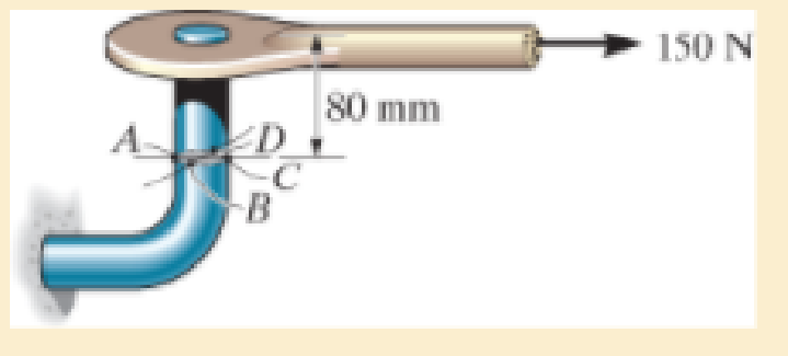
Solve Prob.8-65 for points C and D.
Expert Solution & Answer
Want to see the full answer?
Check out a sample textbook solution
Students have asked these similar questions
Solve Prob. using the maximum shear stress theory.
Determine the normal stress and shear stress acting on the inclined plane AB. Solve the problem using the method of equilibrium described in Sec.
Steel bar in shape,
AAB 600 mm and ABc = DACD3D 1200 mm2 are made of two stages. Determine the displacement at end A in (mm). E = 200 GPa
Chapter 8 Solutions
Mechanics of Materials (10th Edition)
Ch. 8.1 - If it is subjected to an internal pressure of p =...Ch. 8.1 - If it is subjected to an internal pressure of p =...Ch. 8.1 - The thin-walled cylinder can be supported in one...Ch. 8.1 - If the inner diameter of the tank is 22 in., and...Ch. 8.1 - Air pressure in the cylinder is increased by...Ch. 8.1 - Determine the maximum force P that can be exerted...Ch. 8.1 - A boiler is constructed of 8-mm-thick steel plates...Ch. 8.1 - 88. The steel water pipe has an inner diameter of...Ch. 8.1 - The steel water pipe has an inner diameter of 12...Ch. 8.1 - The A-36-steel band is 2 in. wide and is secured...
Ch. 8.1 - The gas pipe line is supported every 20 ft by...Ch. 8.1 - A pressure-vessel head is fabricated by welding...Ch. 8.1 - An A-36-steel hoop has an inner diameter of 23.99...Ch. 8.1 - The ring, having the dimensions shown, is placed...Ch. 8.1 - The inner ring A has an inner radius r1 and outer...Ch. 8.1 - Two hemispheres having an inner radius of 2 ft and...Ch. 8.1 - In order to increase the strength of the pressure...Ch. 8.2 - Show the results on the left segment.Ch. 8.2 - Show the stress that each of these loads produce...Ch. 8.2 - Fundamental Problems F81. Determine the normal...Ch. 8.2 - Show the results in a differential element at the...Ch. 8.2 - Determine the state of stress at point A on the...Ch. 8.2 - Determine the magnitude of the load P that will...Ch. 8.2 - Determine the state of stress at point B. Show the...Ch. 8.2 - Determine the state of stress at point A on the...Ch. 8.2 - Determine the state of stress at point A on the...Ch. 8.2 - Show the results in a differential element at the...Ch. 8.2 - Determine the shortest distance d to the edge of...Ch. 8.2 - The plate has a thickness of 20 mm and P acts...Ch. 8.2 - Plot the distribution of normal stress acting...Ch. 8.2 - Also, plot the normal-stress distribution over the...Ch. 8.2 - If the allowable normal stress for the steel is...Ch. 8.2 - If the applied force P = 1.50 kip, determine the...Ch. 8.2 - Determine the maximum normal stress on the cross...Ch. 8.2 - If the wood has an allowable normal stress of...Ch. 8.2 - Determine the maximum normal stress along section...Ch. 8.2 - Sketch the stress distribution along section aa of...Ch. 8.2 - Sketch the normal-stress distribution acting over...Ch. 8.2 - Determine the state of stress at points A and B,...Ch. 8.2 - If the force of 100 N is applied to the handles,...Ch. 8.2 - Determine the stress components at point A on the...Ch. 8.2 - Determine the stress components at point B on the...Ch. 8.2 - Determine the normal stress developed at points A...Ch. 8.2 - Sketch the normal-stress distribution acting over...Ch. 8.2 - Determine the state of stress at points A and B,...Ch. 8.2 - Determine the state of stress at point A on the...Ch. 8.2 - Determine the state of stress at point B on the...Ch. 8.2 - Determine the state of stress acting at point D....Ch. 8.2 - Determine the state of stress acting at point E....Ch. 8.2 - If it is subjected to the force system shown,...Ch. 8.2 - Solve Prob.840 for point B.Ch. 8.2 - Determine the stress components acting on the...Ch. 8.2 - Determine the stress components acting on the...Ch. 8.2 - Neglect the weight of the block.Ch. 8.2 - Neglect the weight of the block.Ch. 8.2 - He is supported uniformly by two bars, each having...Ch. 8.2 - Determine the state of stress at point A, and show...Ch. 8.2 - Determine the state of stress at point B, and show...Ch. 8.2 - Determine the state of stress at point C, and show...Ch. 8.2 - Determine the maximum radius e at which the load P...Ch. 8.2 - Specify the region to which this load can be...Ch. 8.2 - Determine the smallest force P that can be applied...Ch. 8.2 - The coiled spring is subjected to a force P. If we...Ch. 8.2 - The pins at C and D are at the same location as...Ch. 8.2 - Determine the state of stress at point A, and show...Ch. 8.2 - Determine the state of stress at point B, and show...Ch. 8.2 - Determine the stress components at points A and B...Ch. 8.2 - Determine the stress components at points C and D...Ch. 8.2 - Determine the stress components in the support...Ch. 8.2 - Determine the stress components in the support...Ch. 8.2 - If the force at the ram on the clamp at D is P= 8...Ch. 8.2 - Determine the maximum ram force P that can be...Ch. 8.2 - and an outer radius of 3.00 in. If the face of the...Ch. 8.2 - for points E and F.Ch. 8.2 - Determine the stress components at points A and B...Ch. 8.2 - Solve Prob.8-65 for points C and D.Ch. 8.2 - Due to internal gearing, this causes the block to...Ch. 8.2 - Determine the state of stress at point A and show...Ch. 8.2 - Solve Prob.868 for point B.Ch. 8.2 - Determine the stress components at point A. Sketch...Ch. 8.2 - for the stress components at point B.Ch. 8.2 - Determine the state of stress at point A at...Ch. 8.2 - Determine the state of stress at point B at...Ch. 8 - If it supports a cable loading of 800 lb,...Ch. 8 - Determine the state of stress at point E on the...Ch. 8 - Determine the state of stress at point F on the...Ch. 8 - The suspender arm AE has a square cross-sectional...Ch. 8 - If the cross section of the femur at section aa...Ch. 8 - If it has a mass of 5 kg/m, determine the largest...Ch. 8 - and is used to support the vertical reactions of...Ch. 8 - and is used to support the vertical reactions of...
Knowledge Booster


Learn more about
Need a deep-dive on the concept behind this application? Look no further. Learn more about this topic, mechanical-engineering and related others by exploring similar questions and additional content below.Similar questions
- Repeat Problem 11.2-3 assuming that R= 10 kN · m/rad and L = 2 m.arrow_forward8-3. Draw Mohr’s circle that describes each of the following states of stress for diagram a, b, c.arrow_forwardDetermine the relative displacement of one end of the tapered plate with respect to the other end when it is subjected to an axial load P.arrow_forward
- The composite shaft consists of a mid-section that includes the 1-in.-diameter solid shaft and a tube that is welded to the rigid flanges at A and B. Neglect the thickness of the flanges and determines the angle of twist of end C of the shaft relative to end D. The shaft is subjected to a torque of 800 lb # ft. The material is A-36 steel.arrow_forwardThe truss is made of three A-36 steel members, each having a cross-sectional area of 400 mm2. Determine the horizontal displacement of the roller at C when P = 8 kN.arrow_forwardFor each part of the shaft, determine the torsion T and calculate the corresponding maximum torsional stress. The bearings are frictionless. B is the drive pulley. Shaft diameter is 2 inch.arrow_forward
- Please help :( given: T(sub B) = 80.11, T = 5.67 kN-marrow_forwardThe composite shaft consists of a mid-section that includes the 1-in.-diameter solid shaft and a tube that is welded to the rigid flanges at A and B. Neglect the thickness of the flanges and determine the angle of twist of end C of the shaft relative to end D.The shaft is subjected to a torque of 800 lb.ft.The material is A-36 steel.arrow_forwardIf P is equivalent to 94 kN, the diameter at pin B is Blank 1 mm.arrow_forward
arrow_back_ios
SEE MORE QUESTIONS
arrow_forward_ios
Recommended textbooks for you
 International Edition---engineering Mechanics: St...Mechanical EngineeringISBN:9781305501607Author:Andrew Pytel And Jaan KiusalaasPublisher:CENGAGE L
 Mechanics of Materials (MindTap Course List)Mechanical EngineeringISBN:9781337093347Author:Barry J. Goodno, James M. GerePublisher:Cengage Learning
International Edition---engineering Mechanics: St...
Mechanical Engineering
ISBN:9781305501607
Author:Andrew Pytel And Jaan Kiusalaas
Publisher:CENGAGE L
Mechanics of Materials (MindTap Course List)
Mechanical Engineering
ISBN:9781337093347
Author:Barry J. Goodno, James M. Gere
Publisher:Cengage Learning
Solids: Lesson 53 - Slope and Deflection of Beams Intro; Author: Jeff Hanson;https://www.youtube.com/watch?v=I7lTq68JRmY;License: Standard YouTube License, CC-BY