Mechanics of Materials-Access (1 Sem. )
7th Edition
ISBN: 9780077625191
Author: BEER
Publisher: MCG
expand_more
expand_more
format_list_bulleted
Concept explainers
Videos
Textbook Question
Chapter 8.3, Problem 32P
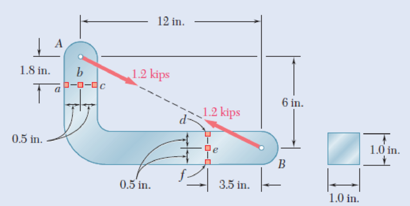
Two 1.2-kip forces are applied to an L-shaped machine element AB as shown. Determine the normal and shearing stresses at (a) point d, (b) point e, (c) point f.
Fig. P8.31 and P8.32
Expert Solution & Answer
Want to see the full answer?
Check out a sample textbook solution
Students have asked these similar questions
Straight rods of 0.30-in. diameter and 200-ft length are sometimes used to clear underground conduits of obstructions or to thread wires through a new conduit. The rods are made of high-strength steel and, for storage and transportation, are wrapped on spools of 5-ft diameter. Assuming that the yield strength is not exceeded, determine (a) the maximum stress in a rod, when the rod, which was initially straight, is wrapped on the spool, (b) the corresponding bending moment in the rod. Use E= 29 * 106 psi.
A steel pipe of 400-mm outer diameter is fabricated from 10-mm-thick plate by welding along a helix that forms an angle of 20°with a plane perpendicular to the axis of the pipe. Knowing that the maximum allowable normal and shearing stresses in the directions respectively normal and tangential to the weld are σ = 60 MPa and τ = 36 MPa, determine the magnitude P of the largest axial force that can be applied to the pipe.
A compressive member of a structure is of 25 mm square cross-section and carries a load of 50 kN. Determine, from first principles, the normal, tangential, and resultant stresses on a plane inclined at 60° to the axis of the bar.
Chapter 8 Solutions
Mechanics of Materials-Access (1 Sem. )
Ch. 8.2 - A W10 = 39 rolled-steel beam supports a load P as...Ch. 8.2 - Solve Prob. 8.1, assuming that P = 22.5 kips and a...Ch. 8.2 - An overhanging W920 449 rolled-steel beam...Ch. 8.2 - Solve Prob. 8.3, assuming that P = 850 kN and a =...Ch. 8.2 - 8.5 and 8.6 (a) Knowing that all = 160 MPa and all...Ch. 8.2 - 8.5 and 8.6 (a) Knowing that all = 160 MPa and all...Ch. 8.2 - 8.7 and 8.8 (a) Knowing that all = 24 ksi and all...Ch. 8.2 - 8.7 and 8.8 (a) Knowing that all = 24 ksi and all...Ch. 8.2 - 8.9 through 8.14 Each of the following problems...Ch. 8.2 - 8.9 through 8.14 Each of the following problems...
Ch. 8.2 - 8.9 through 8.14 Each of the following problems...Ch. 8.2 - Prob. 12PCh. 8.2 - 8.9 through 8.14 Each of the following problems...Ch. 8.2 - 8.9 through 8.14 Each of the following problems...Ch. 8.2 - Determine the smallest allowable diameter of the...Ch. 8.2 - Determine the smallest allowable diameter of the...Ch. 8.2 - Using the notation of Sec. 8.2 and neglecting the...Ch. 8.2 - The 4-kN force is parallel to the x axis, and the...Ch. 8.2 - The vertical force P1 and the horizontal force P2...Ch. 8.2 - The two 500-lb forces are vertical and the force P...Ch. 8.2 - Prob. 21PCh. 8.2 - Prob. 22PCh. 8.2 - The solid shaft AB rotates at 600 rpm and...Ch. 8.2 - The solid shaft AB rotates at 600 rpm and...Ch. 8.2 - The solid shafts ABC and DEF and the gears shown...Ch. 8.2 - Prob. 26PCh. 8.2 - Prob. 27PCh. 8.2 - Prob. 28PCh. 8.2 - The solid shaft AE rotates at 600 rpm and...Ch. 8.2 - The solid shaft AE rotates at 600 rpm and...Ch. 8.3 - Two 1.2-kip forces are applied to an L-shaped...Ch. 8.3 - Two 1.2-kip forces are applied to an L-shaped...Ch. 8.3 - The cantilever beam AB has a rectangular cross...Ch. 8.3 - 8.34 through 8.36 Member AB has a uniform...Ch. 8.3 - 8.34 through 8.36 Member AB has a uniform...Ch. 8.3 - 8.34 through 8.36 Member AB has a uniform...Ch. 8.3 - Prob. 37PCh. 8.3 - Two forces are applied to the pipe AB as shown....Ch. 8.3 - Several forces are applied to the pipe assembly...Ch. 8.3 - The steel pile AB has a 100-mm outer diameter and...Ch. 8.3 - Three forces are applied to a 4-in.-diameter plate...Ch. 8.3 - The steel pipe AB has a 72-mm outer diameter and a...Ch. 8.3 - A 13-kN force is applied as shown to the...Ch. 8.3 - A vertical force P of magnitude 60 lb is applied...Ch. 8.3 - Three forces are applied to the bar shown....Ch. 8.3 - Prob. 46PCh. 8.3 - Three forces are applied to the bar shown....Ch. 8.3 - Three forces are applied to the bar shown....Ch. 8.3 - Two forces are applied to the small post BD as...Ch. 8.3 - Two forces are applied to the small post BD as...Ch. 8.3 - Three forces are applied to the machine component...Ch. 8.3 - Prob. 52PCh. 8.3 - Three steel plates, each 13 mm thick, are welded...Ch. 8.3 - Three steel plates, each 13 mm thick, are welded...Ch. 8.3 - Two forces P1 and P2 are applied as shown in...Ch. 8.3 - Two forces P1 and P2 are applied as shown in...Ch. 8.3 - Prob. 57PCh. 8.3 - Four forces are applied to a W8 28 rolled-steel...Ch. 8.3 - A force P is applied to a cantilever beam by means...Ch. 8.3 - Prob. 60PCh. 8.3 - A 5-kN force P is applied to a wire that is...Ch. 8.3 - Knowing that the structural tube shown has a...Ch. 8.3 - The structural tube shown has a uniform wall...Ch. 8.3 - The structural tube shown has a uniform wall...Ch. 8 - (a) Knowing that all = 24 ksi and all = 14.5 ksi,...Ch. 8 - Neglecting the effect of fillets and of stress...Ch. 8 - Knowing that rods BC and CD are of diameter 24 mm...Ch. 8 - The solid shaft AB rotates at 450 rpm and...Ch. 8 - A 6-kip force is applied to the machine element AB...Ch. 8 - A thin strap is wrapped around a solid rod of...Ch. 8 - A close-coiled spring is made of a circular wire...Ch. 8 - Forces are applied at points A and B of the solid...Ch. 8 - Knowing that the bracket AB has a uniform...Ch. 8 - For the post and loading shown, determine the...Ch. 8 - Knowing that the structural tube shown has a...Ch. 8 - The cantilever beam AB will be installed so that...
Knowledge Booster


Learn more about
Need a deep-dive on the concept behind this application? Look no further. Learn more about this topic, mechanical-engineering and related others by exploring similar questions and additional content below.Similar questions
- A steel pipe of 400-mm outer diameter is fabricated from 10-mmthick plate by welding along a helix that forms an angle of 20° with a plane perpendicular to the axis of the pipe. Knowing that a 300-kN axial force P is applied to the pipe, determine the normal and shearing stresses in directions respectively normal and tangential to the weld.arrow_forwardEach of the four vertical Ilinks has an 8 x 36-mm uniform rectangular cross section and each of the four pins has a 16-mm diameter. Take P= 19 kN. 0.4 m C 0.25 m 0.2 m B. P Determine the average bearing stress at Bin member ABC, knowing that this member has a 10 x 50-mm uniform rectangular cross section. MPa. The average bearing stress at Bin member ABC is.arrow_forwardA spherical gas container made of steel has a 20-ft outer diameter and a wall thickness of 7/16 in. Knowing that the internal pressure is 75 psi, determine the maximum normal stress and the maximum shearing stress in the container.arrow_forward
- A standard-weight steel pipe of 12-in. nominal diameter carries water under a pressure of 400 psi. (a) Knowing that the outside diameter is 12.75 in. and the wall thickness is 0.375 in., determine the maximum tensile stress in the pipe. (b) Solve part a, assuming that an extra-strong pipe is used, of 12.75-in. outside diameter and 0.5-in. wall thickness.arrow_forwardA torque of magnitude T=12 kN·m is applied to the end of a tank containing compressed air under a pressure of 8 MPa. Knowing that the tank has a 180-mm inner diameter and a 12-mm wall thickness, determine the maximum normal stress and the maximum in-plane shearing stress in the tank.arrow_forwardA 40-kN axial load is applied to a short wooden post that is supported by a concrete footing resting on undisturbed soil. Determine (a) the maximum bearing stress on the concrete footing, (b) the size of the footing for which the average bearing stress in the soil is 145 kPa.arrow_forward
- Two steel plates are to be held together by means of 16-mm-diameter high-strength steel bolts fitting snugly inside cylindrical brass spacers.Knowing that the average normal stress must not exceed 200 MPa in the bolts and 130 MPa in the spacers, determine the outer diameter of the spacers that yields the most economical and safe design.arrow_forwardAn offset h must be introduced into a metal tube of 0.75-in. outer diameter and 0.08-in. wall thickness. Knowing that the maximum stress after the offset is introduced must not exceed 4 times the stress in the tube when it was straight, determine the largest offset that can be used.arrow_forwardThe maximum gage pressure is known to be 1150 psi in a spherical steel pressure vessel having a 10-in. outer diameter and a 0.25-in. wall thickness. Knowing that the ultimate stress in the steel used is σU=60 ksi, determine the factor of safety with respect to tensile failure.arrow_forward
- Two forces P can be applied separately or at the same time to a plate that is welded to a solid circular bar of radius r. Determine the largest compressive stress in the circular bar (a) when both forces are applied, (b) when only one of the forces is applied.arrow_forwardIn the structure shown, an 8-mm diameter pin is used at A, and 12- mm diameter pins are used at B and D. Knowing that the ultimate shearing stresses is 100 MPa at all connections and that the ultimate normal stress is 250 MPa in each of the two links joining B and D, determine the allowable load P if an overall factor of safety of 3.0 is desired.arrow_forwardAn open-link chain is obtained by bending low-carbon steel rods of 0.5-in. diameter into the shape shown (Fig. ). Knowing that the chain carries a load of 160 lb, determine (a) the largest tensile and compressive stresses in the straight portion of a link, (b) the distance between the cen-troidal and the neutral axis of a cross sectionarrow_forward
arrow_back_ios
SEE MORE QUESTIONS
arrow_forward_ios
Recommended textbooks for you
 Elements Of ElectromagneticsMechanical EngineeringISBN:9780190698614Author:Sadiku, Matthew N. O.Publisher:Oxford University Press
 Mechanics of Materials (10th Edition)Mechanical EngineeringISBN:9780134319650Author:Russell C. HibbelerPublisher:PEARSON
 Thermodynamics: An Engineering ApproachMechanical EngineeringISBN:9781259822674Author:Yunus A. Cengel Dr., Michael A. BolesPublisher:McGraw-Hill Education
 Control Systems EngineeringMechanical EngineeringISBN:9781118170519Author:Norman S. NisePublisher:WILEY
 Mechanics of Materials (MindTap Course List)Mechanical EngineeringISBN:9781337093347Author:Barry J. Goodno, James M. GerePublisher:Cengage Learning
 Engineering Mechanics: StaticsMechanical EngineeringISBN:9781118807330Author:James L. Meriam, L. G. Kraige, J. N. BoltonPublisher:WILEY
Elements Of Electromagnetics
Mechanical Engineering
ISBN:9780190698614
Author:Sadiku, Matthew N. O.
Publisher:Oxford University Press
Mechanics of Materials (10th Edition)
Mechanical Engineering
ISBN:9780134319650
Author:Russell C. Hibbeler
Publisher:PEARSON
Thermodynamics: An Engineering Approach
Mechanical Engineering
ISBN:9781259822674
Author:Yunus A. Cengel Dr., Michael A. Boles
Publisher:McGraw-Hill Education
Control Systems Engineering
Mechanical Engineering
ISBN:9781118170519
Author:Norman S. Nise
Publisher:WILEY
Mechanics of Materials (MindTap Course List)
Mechanical Engineering
ISBN:9781337093347
Author:Barry J. Goodno, James M. Gere
Publisher:Cengage Learning
Engineering Mechanics: Statics
Mechanical Engineering
ISBN:9781118807330
Author:James L. Meriam, L. G. Kraige, J. N. Bolton
Publisher:WILEY
Everything About COMBINED LOADING in 10 Minutes! Mechanics of Materials; Author: Less Boring Lectures;https://www.youtube.com/watch?v=N-PlI900hSg;License: Standard youtube license