
EBK STATICS AND MECHANICS OF MATERIALS
5th Edition
ISBN: 8220102955295
Author: HIBBELER
Publisher: PEARSON
expand_more
expand_more
format_list_bulleted
Concept explainers
Videos
Textbook Question
Chapter 8.4, Problem 11P
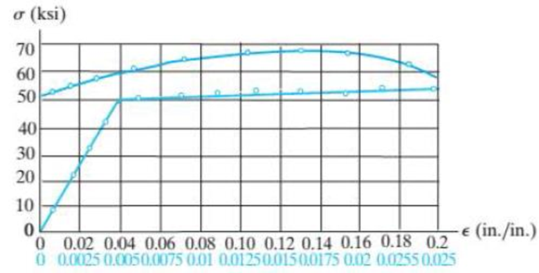
The stress–strain diagram for an aluminum alloy specimen having an original diameter of 0.5 in. and a gage length of 2 in. is given in the figure. If the specimen is loaded until it is stressed to 60 ksi, determine the approximate amount of elastic recovery and the increase in the gage length after it is unloaded.
Probs. 8–10/11/12
Expert Solution & Answer
Want to see the full answer?
Check out a sample textbook solution
Students have asked these similar questions
The stress-strain diagram for an aluminum alloy specimen having an original diameter of 0.5 in. and a gauge length of 2 in. is given in the figure. If the specimen is loaded until it is stressed to 60 ksi, determine the approximate amount of elastic recovery and the increase in the gage length after it is unloaded.
8-21. The elastic portion of the stress-strain diagram for
an aluminum alloy is shown in the figure. The specimen
from which it was obtained has an original diameter of
12.7 mm and a gage length of 50.8 mm. When the applied
load on the specimen is 50 kN, the diameter is 12.67494 mm.
Determine Poisson's ratio for the material.
8-22. The elastic portion of the stress-strain diagram for an
aluminum alloy is shown in the figure. The specimen from
which it was obtained has an original diameter of 12.7 mm
and a gage length of 50.8 mm. If a load of P = 60 kN is
applied to the specimen, determine its new diameter and
length. Take v = 0.35.
σ (MPa)
490
0.007
Probs. 8-21/22
€ (mm/mm)
The elastic portion of the stress–strain diagram for an aluminum alloy is shown in the figure. The specimen from which it was obtained has an original diameter of 12.7 mm and a gage length of 50.8 mm. If a load of P = 60 kN is applied to the specimen, determine its new diameter and length. Taken = 0.35.
Chapter 8 Solutions
EBK STATICS AND MECHANICS OF MATERIALS
Ch. 8.4 - Define a homogeneous material.Ch. 8.4 - Prob. 2FPCh. 8.4 - Prob. 3FPCh. 8.4 - Prob. 4FPCh. 8.4 - Prob. 5FPCh. 8.4 - As the temperature increases the modulus of...Ch. 8.4 - Prob. 7FPCh. 8.4 - Prob. 8FPCh. 8.4 - Prob. 9FPCh. 8.4 - Prob. 10FP
Ch. 8.4 - The material for the 50-mm-long specimen has the...Ch. 8.4 - If the elongation of wire BC is 0.2 mm after the...Ch. 8.4 - A tension test was performed on a steel specimen...Ch. 8.4 - Data taken from a stressstrain test for a ceramic...Ch. 8.4 - Data taken from a stressstrain test for a ceramic...Ch. 8.4 - Prob. 4PCh. 8.4 - The stress-strain diagram for a steel alloy having...Ch. 8.4 - Prob. 6PCh. 8.4 - The rigid beam is supported by a pin at C and an...Ch. 8.4 - The rigid beam is supported by a pin at C and an...Ch. 8.4 - Prob. 9PCh. 8.4 - The stressstrain diagram for an aluminum alloy...Ch. 8.4 - The stressstrain diagram for an aluminum alloy...Ch. 8.4 - Prob. 12PCh. 8.4 - A bar having a length of 5 in. and cross-sectional...Ch. 8.4 - The rigid pipe is supported by a pin at A and an...Ch. 8.4 - The rigid pipe is supported by a pin at A and an...Ch. 8.4 - Prob. 16PCh. 8.4 - The rigid beam is supported by a pin at C and an...Ch. 8.4 - Prob. 18PCh. 8.4 - Prob. 19PCh. 8.6 - A 100 mm long rod has a diameter of 15 mm. If an...Ch. 8.6 - A solid circular rod that is 600 mm long and 20 mm...Ch. 8.6 - Prob. 15FPCh. 8.6 - Prob. 16FPCh. 8.6 - The acrylic plastic rod is 200 mm long and 15 mm...Ch. 8.6 - The plug has a diameter of 30 mm and fits within a...Ch. 8.6 - The elastic portion of the stress-strain diagram...Ch. 8.6 - The elastic portion of the stress-strain diagram...Ch. 8.6 - The brake pads for a bicycle tire arc made of...Ch. 8.6 - The lap joint is connected together using a 1.25...Ch. 8.6 - The lap joint is connected together using a 1.25...Ch. 8.6 - Prob. 27PCh. 8.6 - The shear stress-strain diagram for an alloy is...Ch. 8.6 - Prob. 29PCh. 8 - The elastic portion of the tension stress-strain...Ch. 8 - Prob. 2RPCh. 8 - Prob. 3RPCh. 8 - Prob. 4RPCh. 8 - Prob. 5RPCh. 8 - Prob. 6RPCh. 8 - The stress-strain diagram for polyethylene, which...Ch. 8 - The pipe with two rigid caps attached to its ends...Ch. 8 - Prob. 9RPCh. 8 - Prob. 10RP
Knowledge Booster


Learn more about
Need a deep-dive on the concept behind this application? Look no further. Learn more about this topic, mechanical-engineering and related others by exploring similar questions and additional content below.Similar questions
- *84 The stress-strain diagram for a metal alloy having an original diameter of 12 mm and a gauge length of 50 mm is given in the figure. Determine approximately the modulus of elasticity for the material, the load on the specimen that causes yielding, and the ultimate load the specimen will support. a (MPa) 600 500 400 300 200 100 -e(mm/mm) o 004 008 a12 0.16 0.20 024 0.28 O 0005 0.001 0.0015 0002 0.0025 0.003 0.0035arrow_forwardThe stress-strain diagram for a steel alloy having an original diameter of 0.5 in. and a gauge length of 2 in. is given in the figure. Determine approximately the modulus of elasticity for the material, the load on the specimen that causes yielding, and the ultimate load the specimen will support.arrow_forwardR8-1. The elastic portion of the tension stress-strain diagram for an aluminum alloy is shown in the figure. The specimen used for the test has a gauge length of 50 mm and a diameter of 12.5 mm. When the applied load is 40 kN, the new diameter of the specimen is 12.4800 mm. Compute the shear modulus G, for the aluminum. a (MPa) 350 (mm/mm) 0.00480arrow_forward
- The elastic portion of the tension stress–strain diagram for an aluminum alloy is shown in the figure. The specimen used for the test has a gage length of 2 in. and a diameter of 0.5 in. If the applied load is 10 kip, determine the new diameter of the specimen. The shear modulus is Gal = 3.811032 ksi.arrow_forwardThe elastic portion of the tension stress–strain diagram for an aluminum alloy is shown in the figure. The specimen used for the test has a gage length of 2 in. and a diameter of 0.5 in. When the applied load is 9 kip, the new diameter of the specimen is 0.49935 in. Calculate the shear modulus Gal for the aluminum.arrow_forwardThe elastic portion of the stress-strain diagram for an aluminum alloy is shown in the figure. The specimen from which it was obtained has an original diameter of 12.7 mm and a gage length of 50.8 mm. If a load of P=60 kN is applied to the specimen, determine its new diameter and length. Take v = 0.35. o (MPa) 490 e (mm/mm) 0.007arrow_forward
- 8-22. The elastic portion of the stress-strain diagram for an aluminum alloy is shown in the figure. The specimen from which it was obtained has an original diameter of 12.7 mm and a gage length of 50.8 mm. If a load of P - 60 kN is applied to the specimen, determine its new diameter and length. Take v-0.35. a (MPa) 490 (mm/mm) 0.007arrow_forwardProblem 7 The shear stress-strain diagram for an alloy is shown in the figure. If a bolt having a diameter of 0.25 in. is made of this material and used in the lap joint, determine the modulus of elasticity E and the force P required to cause the material to yield. Take v=0.3. 7 (ksi) Ty= 50 0.004 y (rad)arrow_forwardThe column is loaded with an axial force of P = 2,050 kN through a rigid endplate. Determine the deformation of the column in mm.arrow_forward
- Simple stress and strain pleasee helparrow_forwardNylon strips are fused to glass plates. When moderately heated the nylon will become soft while the glass stays approximately rigid. Determine the average shear strain in the nylon due to the load P when the assembly deforms as indicated. 2 mm P. 3 mm 5 mm 3 mm 5 mm 3 mmarrow_forwardA tension test was performed on a steel specimen having an original diameter of 12.5 mm and gauge length of 50 mm. The data is listed in the table. Plot the stress–strain diagram and determine approximately the modulus of elasticity, the yield stress, the ultimate stress, and the rupture stress. Use a scale of 25 mm = 140 MPa and 25 mm = 0.05 mm/mm. Redraw the elastic region, using the same stress scale but a strain scale of 25 mm = 0.001 mm/mm.arrow_forward
arrow_back_ios
SEE MORE QUESTIONS
arrow_forward_ios
Recommended textbooks for you
 Mechanics of Materials (MindTap Course List)Mechanical EngineeringISBN:9781337093347Author:Barry J. Goodno, James M. GerePublisher:Cengage Learning
Mechanics of Materials (MindTap Course List)
Mechanical Engineering
ISBN:9781337093347
Author:Barry J. Goodno, James M. Gere
Publisher:Cengage Learning
Material Properties 101; Author: Real Engineering;https://www.youtube.com/watch?v=BHZALtqAjeM;License: Standard YouTube License, CC-BY