
EBK STATICS AND MECHANICS OF MATERIALS
5th Edition
ISBN: 8220102955295
Author: HIBBELER
Publisher: PEARSON
expand_more
expand_more
format_list_bulleted
Concept explainers
Videos
Textbook Question
Chapter 8.6, Problem 21P
The plug has a diameter of 30 mm and fits within a rigid sleeve having an inner diameter of 32 mm. Both the plug and the sleeve are 50 mm long. Determine the axial pressure p that must be applied to the top of the plug to cause it to contact the sides of the sleeve. Also, how far must the plug be compressed downward in order to do this? The Plug is made from a material for which E = 5 Mpa, v = 0.45.
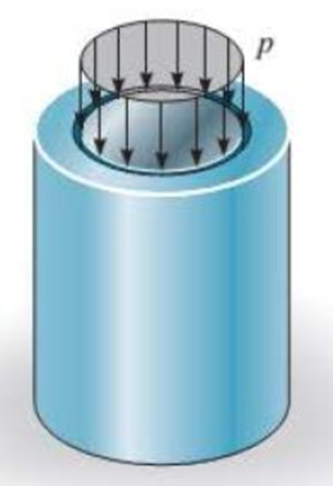
Prob 8–21.
Expert Solution & Answer
Want to see the full answer?
Check out a sample textbook solution
Students have asked these similar questions
8-23. The plug has a diameter of 30 mm and fits within a
rigid sleeve having an inner diameter of 32 mm. Both the
plug and the sleeve are 50 mm long. Determine the axial
pressure p that must be applied to the top of the plug to
cause it to contact the sides of the sleeve. Alsa, how far must
the plug be compressed downward in order to do this? The
plug is made from a material for which E-5 MPa, v -0.45.
If the bolt length is 220 mmmm and the sleeve length is 200 mmmm, determine the tension in the bolt when a force of 50 kNkN is applied to the brackets.
Express your answer to three significant figures and include appropriate units.
Given: The bolt AB in (Figure 1) has a diameter of 21 mmmm and passes through a sleeve that has an inner diameter of 42 mmmm and an outer diameter of 52 mmmm. The bolt and sleeve are made of A-36 steel and are secured to the rigid brackets as shown.
The plastic 50-mm diameter rod is placed in a 51-mm-diameter hole with rigid walls. Determine the change in the length of the rod after the 8 kN load is applied. Use E = 40 MPa and v=0.45 for the rod.
Chapter 8 Solutions
EBK STATICS AND MECHANICS OF MATERIALS
Ch. 8.4 - Define a homogeneous material.Ch. 8.4 - Prob. 2FPCh. 8.4 - Prob. 3FPCh. 8.4 - Prob. 4FPCh. 8.4 - Prob. 5FPCh. 8.4 - As the temperature increases the modulus of...Ch. 8.4 - Prob. 7FPCh. 8.4 - Prob. 8FPCh. 8.4 - Prob. 9FPCh. 8.4 - Prob. 10FP
Ch. 8.4 - The material for the 50-mm-long specimen has the...Ch. 8.4 - If the elongation of wire BC is 0.2 mm after the...Ch. 8.4 - A tension test was performed on a steel specimen...Ch. 8.4 - Data taken from a stressstrain test for a ceramic...Ch. 8.4 - Data taken from a stressstrain test for a ceramic...Ch. 8.4 - Prob. 4PCh. 8.4 - The stress-strain diagram for a steel alloy having...Ch. 8.4 - Prob. 6PCh. 8.4 - The rigid beam is supported by a pin at C and an...Ch. 8.4 - The rigid beam is supported by a pin at C and an...Ch. 8.4 - Prob. 9PCh. 8.4 - The stressstrain diagram for an aluminum alloy...Ch. 8.4 - The stressstrain diagram for an aluminum alloy...Ch. 8.4 - Prob. 12PCh. 8.4 - A bar having a length of 5 in. and cross-sectional...Ch. 8.4 - The rigid pipe is supported by a pin at A and an...Ch. 8.4 - The rigid pipe is supported by a pin at A and an...Ch. 8.4 - Prob. 16PCh. 8.4 - The rigid beam is supported by a pin at C and an...Ch. 8.4 - Prob. 18PCh. 8.4 - Prob. 19PCh. 8.6 - A 100 mm long rod has a diameter of 15 mm. If an...Ch. 8.6 - A solid circular rod that is 600 mm long and 20 mm...Ch. 8.6 - Prob. 15FPCh. 8.6 - Prob. 16FPCh. 8.6 - The acrylic plastic rod is 200 mm long and 15 mm...Ch. 8.6 - The plug has a diameter of 30 mm and fits within a...Ch. 8.6 - The elastic portion of the stress-strain diagram...Ch. 8.6 - The elastic portion of the stress-strain diagram...Ch. 8.6 - The brake pads for a bicycle tire arc made of...Ch. 8.6 - The lap joint is connected together using a 1.25...Ch. 8.6 - The lap joint is connected together using a 1.25...Ch. 8.6 - Prob. 27PCh. 8.6 - The shear stress-strain diagram for an alloy is...Ch. 8.6 - Prob. 29PCh. 8 - The elastic portion of the tension stress-strain...Ch. 8 - Prob. 2RPCh. 8 - Prob. 3RPCh. 8 - Prob. 4RPCh. 8 - Prob. 5RPCh. 8 - Prob. 6RPCh. 8 - The stress-strain diagram for polyethylene, which...Ch. 8 - The pipe with two rigid caps attached to its ends...Ch. 8 - Prob. 9RPCh. 8 - Prob. 10RP
Knowledge Booster


Learn more about
Need a deep-dive on the concept behind this application? Look no further. Learn more about this topic, mechanical-engineering and related others by exploring similar questions and additional content below.Similar questions
- The 10-mm-diameter bolt is made of an aluminum alloy. It fits through a magnesium sleeve that has an inner diameter of 15 mm and an outer diameter of 25 mm. The original lengths of the bolt and sleeve are 80 mm and 50 mm, respectively. If after the nut on the bolt is tightened the tension in the bolt is 10 kN, determine the change of volume of the bolt and the new length of the sleeve. Wherein both materials behave linearly elastic. Assume the material at A is rigid. E = 68.9 GPa, Emg = 44.6 GPa, Ga = 26 GPa, Gmg = 18 GPa.arrow_forwardThe 10-mm-diameter bolt is made of an aluminum alloy. It fits through a magnesium sleeve that has an inner diameter of 15 mm and an outer diameter of 25 mm. The original lengths of the bolt and sleeve are 80 mm and 50 mm, respectively. If after the nut on the bolt is tightened the tension in the bolt is 10 kN, determine the change in dimension of the cross-section of the bolt and the sleeve. Assume the material at A is rigid. E = 70 GPa, Emg = 45 GPa, Ga = 26 GPa, Gmg = 17 GPa.arrow_forwardAn A-36-steel hoop has an inner diameter of 23.99 in., a thickness of 0.25 in., and a width of 1 in. If it and the 24-in.-diameter A rigid cylinder has a temperature of 65° F, determine the temperature to which the hoop should be heated in order for it to just slip over the cylinder. What is the pressure the hoop exerts on the cylinder, and the tensile stress in the ring when it cools back down to 65° F?arrow_forward
- The gas storage tank is fabricated by bolting together two half cylindrical thin shells and two hemispherical shells as shown. If the tank is designed to withstand a pressure of 3 MPa, determine the required minimum thickness of the cylinder and hemispherical shells and the minimum required number of bolts for each hemispherical cap. The tank and the 25 mm diameter bolts are made from material having an allowable normal stress of 150 MPa and 250 MPa, respectively. The tank has an inner diameter of 4 m.arrow_forwardThe aluminum cube (600x600x600 mm) is put inside a hole of a rigid boundary as shown below. Initially, there is a gap of 0.2 mm between the cube and the rigid boundary. Determine the new dimensions of the cube if a stress of 100 MPa is applied on the top face of the cube and the temperature of the cube increased by 35°C. For aluminum: Ea=73 GPa, va-0.35, aai = 23*10C y. o=100 MPa Rigid boundary Rigid boundary Aluminum cube 600 mm- 0.2 mmarrow_forwardA 20-mm-wide block is firmly bonded to rigid plates at its top and bottom. When the force P is applied the block deforms into the shape shown by the dashed line. Determine the magnitude of P. The block’s material has a modulus of rigidity of G = 26 GPa. Assume that the material does not yield and use small-angle analysis.arrow_forward
- The bar has a cross-sectional area A, length L, modulus of elasticity E, and coefficient of thermal expansion a. The temperature of the bar changes uniformly along its length from TA at A to TB at B so that at any point x alongthe bar T = TA + x(TB - TA)>L. Determine the force the bar exerts on the rigid walls. Initially, no axial force is in the bar and the bar has a temperature of TA.arrow_forwardA steel bar 300 mm long, 50 mm wide and 40 mm thick is subjected to a pull of 300 kN in the direction of length. Determine the change in volume. Take E = 2x10⁵ N/mm2and μ= 0.25.arrow_forwardThe cylindrical vessel with hemispherical end caps is made of steel and pressurized to 3.6 MPa. The vessel has a uniform thickness of 18 mm, an outer diameter of 400 mm and effective length of 600 mm. If this vessel is to be replaced with a spherical vessel of equal pressure and equal material strength, determine its thickness.arrow_forward
- 3. The rigid bar ABC and EFG are supported by pins at A and G. The vertical rods are made of steel (rod DC and rod BE). Determine the vertical displacement at C if the change in temperature is 50°C. Use a = 0.0000117/°C and E = 200 GPa. Neglect the weight of the members. A=125 sq. mm L= 2 m A 2 m B 2 m A=135 sq. mm L = 3 m E G 2 m F 3 m 50 kNarrow_forwardWhen the temperature is 10°C, the two rods are separated by a 0.5-mm 0.5 mm gap as shown. If the temperature rises to 90°C, determine (a) the normal stress in each rod, 300 mm 250 mm (b) the change in length of the stainless steel rod. A B Aluminum A = 2000 mm? E = 75 GPa a = 23 x 10-6/°C Stainless steel A = 800 mm? E = 190 GPa a = 17.3 x 10-/°Carrow_forwardThe center rod CD of the assembly is heated from T₁ = 30 °C to T₂ = 165 °C using electrical resistance heating. At the lower temperature T₁ the gap between C and the rigid bar is 0.7 mm. Rods AB and EF are made of steel, and each has a cross-sectional area of 125 mm². CD is made of aluminum and has a cross-sectional area of 375 mm². Est = 200 GPa, Eal = 70 GPa, and cal = 23 (10-) /°C. (Figure 1) Figure 0.7 mm 240 mm 300 mm Determine the force in the rod AB caused by the increase in temperature. Express your answer to three significant figures and include the appropriate units. FAB = Submit Part B FEF= _O Submit μA Value Request Answer Determine the force in the rod EF caused by the increase in temperature. Express your answer to three significant figures and include the appropriate units. |μA Value Units Request Answer ? Units ?arrow_forward
arrow_back_ios
SEE MORE QUESTIONS
arrow_forward_ios
Recommended textbooks for you
 Elements Of ElectromagneticsMechanical EngineeringISBN:9780190698614Author:Sadiku, Matthew N. O.Publisher:Oxford University Press
 Mechanics of Materials (10th Edition)Mechanical EngineeringISBN:9780134319650Author:Russell C. HibbelerPublisher:PEARSON
 Thermodynamics: An Engineering ApproachMechanical EngineeringISBN:9781259822674Author:Yunus A. Cengel Dr., Michael A. BolesPublisher:McGraw-Hill Education
 Control Systems EngineeringMechanical EngineeringISBN:9781118170519Author:Norman S. NisePublisher:WILEY
 Mechanics of Materials (MindTap Course List)Mechanical EngineeringISBN:9781337093347Author:Barry J. Goodno, James M. GerePublisher:Cengage Learning
 Engineering Mechanics: StaticsMechanical EngineeringISBN:9781118807330Author:James L. Meriam, L. G. Kraige, J. N. BoltonPublisher:WILEY
Elements Of Electromagnetics
Mechanical Engineering
ISBN:9780190698614
Author:Sadiku, Matthew N. O.
Publisher:Oxford University Press
Mechanics of Materials (10th Edition)
Mechanical Engineering
ISBN:9780134319650
Author:Russell C. Hibbeler
Publisher:PEARSON
Thermodynamics: An Engineering Approach
Mechanical Engineering
ISBN:9781259822674
Author:Yunus A. Cengel Dr., Michael A. Boles
Publisher:McGraw-Hill Education
Control Systems Engineering
Mechanical Engineering
ISBN:9781118170519
Author:Norman S. Nise
Publisher:WILEY
Mechanics of Materials (MindTap Course List)
Mechanical Engineering
ISBN:9781337093347
Author:Barry J. Goodno, James M. Gere
Publisher:Cengage Learning
Engineering Mechanics: Statics
Mechanical Engineering
ISBN:9781118807330
Author:James L. Meriam, L. G. Kraige, J. N. Bolton
Publisher:WILEY
EVERYTHING on Axial Loading Normal Stress in 10 MINUTES - Mechanics of Materials; Author: Less Boring Lectures;https://www.youtube.com/watch?v=jQ-fNqZWrNg;License: Standard YouTube License, CC-BY