
EBK STATICS AND MECHANICS OF MATERIALS
5th Edition
ISBN: 8220102955295
Author: HIBBELER
Publisher: PEARSON
expand_more
expand_more
format_list_bulleted
Concept explainers
Videos
Textbook Question
Chapter 8.4, Problem 13P
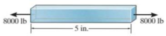
A bar having a length of 5 in. and cross-sectional area of 0.7 in2 is subjected to an axial force of 8000 lb. If the bar stretches 0.002 in., determine the modulus of elasticity of the material. The material has linear elastic behavior.
Prob. 8–13
Expert Solution & Answer
Want to see the full answer?
Check out a sample textbook solution
Students have asked these similar questions
The pole is supported by a pin at B and A-36 steel guy wire AC. If the wire has a diameter of
0.2. Modulus of Elasticity of Steel = 200GPA or 29x103 ksi Poisson's ratio of steel=0.321
a. Determine how much the wire stretches when the horizontal force acts on the pole.
3 ft
30
D 2.5 kip
4 ft
B
b. Determine the change in the wire's radius
c. At what angle is the principal stresses on pole BC? Use Mohr's Circle.
d. What is the principal stress in pol BC? Use Mohr's Circle
e. Draw the stresses on a unit element acting on 35-degree clockwise direction of pole BC. Use
Mohr's Circle.
f. What are the principal stresses in point D? Use Mohr's Circle. (answer in ksi)
g. At what angle is the principal stresses acting on point D? Use Mohr 's Circle.
h. Draw the stresses on a unit element acting on 35degree-clockwise direction of point D. Use Mohr's
Circle. (answer in ksi)
The two bars are made of a material that has the stress-strain diagram shown. If the cross-sectional area of bar AB is 1.5 in2 and BC is 4 in2, determine the largest force P that can be supported before any member fractures. Assume that buckling does not occur.
The 200 mm long and 20 mm diameter solid circular rod is subjected to an axial force of P. P = 400 and δ = 1.6. ElasticityCalculate the modulus E and the shear modulus G. Take 0.3 Poisson's ratio.
Chapter 8 Solutions
EBK STATICS AND MECHANICS OF MATERIALS
Ch. 8.4 - Define a homogeneous material.Ch. 8.4 - Prob. 2FPCh. 8.4 - Prob. 3FPCh. 8.4 - Prob. 4FPCh. 8.4 - Prob. 5FPCh. 8.4 - As the temperature increases the modulus of...Ch. 8.4 - Prob. 7FPCh. 8.4 - Prob. 8FPCh. 8.4 - Prob. 9FPCh. 8.4 - Prob. 10FP
Ch. 8.4 - The material for the 50-mm-long specimen has the...Ch. 8.4 - If the elongation of wire BC is 0.2 mm after the...Ch. 8.4 - A tension test was performed on a steel specimen...Ch. 8.4 - Data taken from a stressstrain test for a ceramic...Ch. 8.4 - Data taken from a stressstrain test for a ceramic...Ch. 8.4 - Prob. 4PCh. 8.4 - The stress-strain diagram for a steel alloy having...Ch. 8.4 - Prob. 6PCh. 8.4 - The rigid beam is supported by a pin at C and an...Ch. 8.4 - The rigid beam is supported by a pin at C and an...Ch. 8.4 - Prob. 9PCh. 8.4 - The stressstrain diagram for an aluminum alloy...Ch. 8.4 - The stressstrain diagram for an aluminum alloy...Ch. 8.4 - Prob. 12PCh. 8.4 - A bar having a length of 5 in. and cross-sectional...Ch. 8.4 - The rigid pipe is supported by a pin at A and an...Ch. 8.4 - The rigid pipe is supported by a pin at A and an...Ch. 8.4 - Prob. 16PCh. 8.4 - The rigid beam is supported by a pin at C and an...Ch. 8.4 - Prob. 18PCh. 8.4 - Prob. 19PCh. 8.6 - A 100 mm long rod has a diameter of 15 mm. If an...Ch. 8.6 - A solid circular rod that is 600 mm long and 20 mm...Ch. 8.6 - Prob. 15FPCh. 8.6 - Prob. 16FPCh. 8.6 - The acrylic plastic rod is 200 mm long and 15 mm...Ch. 8.6 - The plug has a diameter of 30 mm and fits within a...Ch. 8.6 - The elastic portion of the stress-strain diagram...Ch. 8.6 - The elastic portion of the stress-strain diagram...Ch. 8.6 - The brake pads for a bicycle tire arc made of...Ch. 8.6 - The lap joint is connected together using a 1.25...Ch. 8.6 - The lap joint is connected together using a 1.25...Ch. 8.6 - Prob. 27PCh. 8.6 - The shear stress-strain diagram for an alloy is...Ch. 8.6 - Prob. 29PCh. 8 - The elastic portion of the tension stress-strain...Ch. 8 - Prob. 2RPCh. 8 - Prob. 3RPCh. 8 - Prob. 4RPCh. 8 - Prob. 5RPCh. 8 - Prob. 6RPCh. 8 - The stress-strain diagram for polyethylene, which...Ch. 8 - The pipe with two rigid caps attached to its ends...Ch. 8 - Prob. 9RPCh. 8 - Prob. 10RP
Knowledge Booster


Learn more about
Need a deep-dive on the concept behind this application? Look no further. Learn more about this topic, mechanical-engineering and related others by exploring similar questions and additional content below.Similar questions
- The rigid beam is supported by a pin at C and an A-36 steel guy wire AB. 30 10 ft Part A If the wire has a diameter of 0.5 in., determine how much it stretches when a distributed load of 190 lb/ft acts on the beam. The material remains elastic. Express your answer to three significant figures and include appropriate units. µA ? SAB = 0.02668 inarrow_forwardThe rigid bar is pinned at A and supported by two aluminum rods, each having a diameter of 1 in. and a modulus of elasticity Eal = 10(103) ksi. If the bar is initially vertical, determine the displacement of the end B when the force of 2 kip is applied.arrow_forward8-22. The elastic portion of the stress-strain diagram for an aluminum alloy is shown in the figure. The specimen from which it was obtained has an original diameter of 12.7 mm and a gage length of 50.8 mm. If a load of P - 60 kN is applied to the specimen, determine its new diameter and length. Take v-0.35. a (MPa) 490 (mm/mm) 0.007arrow_forward
- 1- For the tapered bar shown with cross sectional areas A₁=0.02 m² and A=0.01 m² at each end. The bar is made from a material with an elastic modulus of 200 GPa and is subjected to axial force of 4500 N. Determine the nodal displacement at the free end using two equal length elements. E L-1.0m P-4000Narrow_forwardIf the yield strength for the bar is Gyield = 220 MPa, determine the maximum axial force P that can be applied to the bar. P 40 mm 5 mm 20 mm r = 10 mm 20 mm Parrow_forwardA bar has a length of 200 mm and cross-sectional area of 7500 mm2. Determine the modulus ofelasticity of the material if it is subjected to an axial tensile load of 50 kN and stretches 0.075 mm.The material has linear-elastic behavior.arrow_forward
- 8-21. The elastic portion of the stress-strain diagram for an aluminum alloy is shown in the figure. The specimen from which it was obtained has an original diameter of 12.7 mm and a gage length of 50.8 mm. When the applied load on the specimen is 50 kN, the diameter is 12.67494 mm. Determine Poisson's ratio for the material. (MPa) 490 (mm/mm) 0.007arrow_forwardThe pipe with two rigid caps attached to its ends is subjected to an axial force P. If the pipe is made from a material having a modulus of elasticity E and Poisson’s ratio n, determine the change in volume of the material.arrow_forwardThe shear stress–strain diagram for an alloy is shown in the figure. If a bolt having a diameter of 0.25 in. is made of this material and used in the lap joint, determine the modulus of elasticity E and the force P required to cause the material to yield. Take n = 0.3.arrow_forward
- The steel bar has the original dimensions shown in the figure. If it is subjected to an axial load of 50 kN, determine the change in its length and its new cross-sectional dimensions at section a–a. Est = 200 GPa, nst = 0.29.arrow_forward3–26. The thin-walled tube is subjected to an axial force of 40 kN. If the tube elongates 3 mm and its circumference decreases 0.09 mm, determine the modulus of elasticity, Poisson's ratio, and the shear modulus of the tube's material. The material behaves elastically. 40 kN 900 mm | 10 mm 40 kN 12.5 mmarrow_forwardThe elastic portion of the stress-strain diagram for an aluminum alloy is shown in the figure. The specimen from which it was obtained has an original diameter of 12.7 mm and a gage length of 50.8 mm. If a load of P=60 kN is applied to the specimen, determine its new diameter and length. Take v = 0.35. o (MPa) 490 e (mm/mm) 0.007arrow_forward
arrow_back_ios
SEE MORE QUESTIONS
arrow_forward_ios
Recommended textbooks for you
 Elements Of ElectromagneticsMechanical EngineeringISBN:9780190698614Author:Sadiku, Matthew N. O.Publisher:Oxford University Press
 Mechanics of Materials (10th Edition)Mechanical EngineeringISBN:9780134319650Author:Russell C. HibbelerPublisher:PEARSON
 Thermodynamics: An Engineering ApproachMechanical EngineeringISBN:9781259822674Author:Yunus A. Cengel Dr., Michael A. BolesPublisher:McGraw-Hill Education
 Control Systems EngineeringMechanical EngineeringISBN:9781118170519Author:Norman S. NisePublisher:WILEY
 Mechanics of Materials (MindTap Course List)Mechanical EngineeringISBN:9781337093347Author:Barry J. Goodno, James M. GerePublisher:Cengage Learning
 Engineering Mechanics: StaticsMechanical EngineeringISBN:9781118807330Author:James L. Meriam, L. G. Kraige, J. N. BoltonPublisher:WILEY
Elements Of Electromagnetics
Mechanical Engineering
ISBN:9780190698614
Author:Sadiku, Matthew N. O.
Publisher:Oxford University Press
Mechanics of Materials (10th Edition)
Mechanical Engineering
ISBN:9780134319650
Author:Russell C. Hibbeler
Publisher:PEARSON
Thermodynamics: An Engineering Approach
Mechanical Engineering
ISBN:9781259822674
Author:Yunus A. Cengel Dr., Michael A. Boles
Publisher:McGraw-Hill Education
Control Systems Engineering
Mechanical Engineering
ISBN:9781118170519
Author:Norman S. Nise
Publisher:WILEY
Mechanics of Materials (MindTap Course List)
Mechanical Engineering
ISBN:9781337093347
Author:Barry J. Goodno, James M. Gere
Publisher:Cengage Learning
Engineering Mechanics: Statics
Mechanical Engineering
ISBN:9781118807330
Author:James L. Meriam, L. G. Kraige, J. N. Bolton
Publisher:WILEY
EVERYTHING on Axial Loading Normal Stress in 10 MINUTES - Mechanics of Materials; Author: Less Boring Lectures;https://www.youtube.com/watch?v=jQ-fNqZWrNg;License: Standard YouTube License, CC-BY