
Statics and Mechanics of Materials, Student Value Edition (5th Edition)
5th Edition
ISBN: 9780134382890
Author: Russell C. Hibbeler
Publisher: PEARSON
expand_more
expand_more
format_list_bulleted
Concept explainers
Videos
Textbook Question
Chapter 8.4, Problem 5P
The stress-strain diagram for a steel alloy having an original diameter of 0.5 in. and a gage length of 2 in. is given in the figure. If the specimen is loaded until it is stressed to 70 ksi, determine the approximate amount of elastic recovery and the increase in the gage length after it is unloaded.
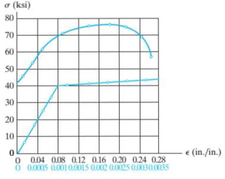
Prob. 8-5
Expert Solution & Answer
Want to see the full answer?
Check out a sample textbook solution
Students have asked these similar questions
The bolt has a diameter of 10 mm, and the arm AB has a rectangular cross section that is 12 mm wide by 7 mm thick. Determine the strain energy in the arm due to bending and in the bolt due to axial force. The bolt is tightened so that it has a tension of 500 N. Both members are made of A-36 steel. Neglect the hole in the arm.
The A-36 steel bar consists of two segments, one ofcircular cross section of radius r, and one of square crosssection. If the bar is subjected to the axial loading of P,determine the dimensions a of the square segment so thatthe strain energy within the square segment is the same asin the circular segment.
The spherical pressure vessel has an inner diameter of 2 m and a thickness of 10 mm. A strain gage having a length of 20 mm is attached to it, and it is observed to increase in length by 0.012 mm when the vessel is pressurized. Determine the pressure causing this deformation, and find the maximum in-plane shear stress, and the absolute maximum shear stress at a point on theouter surface of the vessel. The material is steel, for which Est = 200 GPa and nst = 0.3.
Chapter 8 Solutions
Statics and Mechanics of Materials, Student Value Edition (5th Edition)
Ch. 8.4 - Define a homogeneous material.Ch. 8.4 - Prob. 2FPCh. 8.4 - Prob. 3FPCh. 8.4 - Prob. 4FPCh. 8.4 - Prob. 5FPCh. 8.4 - As the temperature increases the modulus of...Ch. 8.4 - Prob. 7FPCh. 8.4 - Prob. 8FPCh. 8.4 - Prob. 9FPCh. 8.4 - Prob. 10FP
Ch. 8.4 - The material for the 50-mm-long specimen has the...Ch. 8.4 - If the elongation of wire BC is 0.2 mm after the...Ch. 8.4 - A tension test was performed on a steel specimen...Ch. 8.4 - Data taken from a stressstrain test for a ceramic...Ch. 8.4 - Data taken from a stressstrain test for a ceramic...Ch. 8.4 - Prob. 4PCh. 8.4 - The stress-strain diagram for a steel alloy having...Ch. 8.4 - Prob. 6PCh. 8.4 - The rigid beam is supported by a pin at C and an...Ch. 8.4 - The rigid beam is supported by a pin at C and an...Ch. 8.4 - Prob. 9PCh. 8.4 - The stressstrain diagram for an aluminum alloy...Ch. 8.4 - The stressstrain diagram for an aluminum alloy...Ch. 8.4 - Prob. 12PCh. 8.4 - A bar having a length of 5 in. and cross-sectional...Ch. 8.4 - The rigid pipe is supported by a pin at A and an...Ch. 8.4 - The rigid pipe is supported by a pin at A and an...Ch. 8.4 - Prob. 16PCh. 8.4 - The rigid beam is supported by a pin at C and an...Ch. 8.4 - Prob. 18PCh. 8.4 - Prob. 19PCh. 8.6 - A 100 mm long rod has a diameter of 15 mm. If an...Ch. 8.6 - A solid circular rod that is 600 mm long and 20 mm...Ch. 8.6 - Prob. 15FPCh. 8.6 - Prob. 16FPCh. 8.6 - The acrylic plastic rod is 200 mm long and 15 mm...Ch. 8.6 - The plug has a diameter of 30 mm and fits within a...Ch. 8.6 - The elastic portion of the stress-strain diagram...Ch. 8.6 - The elastic portion of the stress-strain diagram...Ch. 8.6 - The brake pads for a bicycle tire arc made of...Ch. 8.6 - The lap joint is connected together using a 1.25...Ch. 8.6 - The lap joint is connected together using a 1.25...Ch. 8.6 - Prob. 27PCh. 8.6 - The shear stress-strain diagram for an alloy is...Ch. 8.6 - Prob. 29PCh. 8 - The elastic portion of the tension stress-strain...Ch. 8 - Prob. 2RPCh. 8 - Prob. 3RPCh. 8 - Prob. 4RPCh. 8 - Prob. 5RPCh. 8 - Prob. 6RPCh. 8 - The stress-strain diagram for polyethylene, which...Ch. 8 - The pipe with two rigid caps attached to its ends...Ch. 8 - Prob. 9RPCh. 8 - Prob. 10RP
Knowledge Booster


Learn more about
Need a deep-dive on the concept behind this application? Look no further. Learn more about this topic, mechanical-engineering and related others by exploring similar questions and additional content below.Similar questions
- The vertical steel rod has a constant diameter of 32 mm and a length of 400 mm. is hanged from a rigid fixing. A mass is gently placed onto a collar which is attached to the lower end of the rod. The strain energy stored in the steel is 0.400 x 10-³. If Esteet = 209 GPa, 1.1 Determine the gradually applied load and magnitude of the mass. 1.2 Calculate the maximum stress in the rod when gradually applied. 1.3 Determine the magnitude of the mass when the mass is suddenly applied. 1.4 Calculate the extension of the rod when suddenly applied.arrow_forwardThe bar has a cross-sectional area of 0.5 in2 and is made of a material that has a stress-strain diagram that can be approximated by the two line segments. Determine the elongation of the bar due to the applied loading.arrow_forwardThe strain at point A on the bracket has normal components 250x10-6 and 550x10-6 in x and y directions, respectively and shear component -600 x10-6 in x-y plane. Determine the absolute maximum shear strain in 10-6 unit.arrow_forward
- A single strain gage, placed in the vertical plane on the outer surface and at an angle 60° to the axis of the pipe, gives a reading at point A of PA = -250(10-6). Determine the principal strains in the pipe at this point. The pipe has an outer diameter of 1 in. and an inner diameter of 0.6 in. and is made of C86100 bronze.arrow_forwardThe polysulfone block is glued at its top and bottom to the rigid plates. If a tangential force, applied to the top plate, causes the material to deform so that its sides are described by the equation y = 3.56 x1>4, determine the shear strain at the corners A and B.arrow_forwardThe steel shaft has a radius of 15 mm. Determine the torque T in the shaft if the two strain gages, attached to the surface of the shaft, report strains of Px = -80(10-6) and Py = 80(10-6). Also, determine the strains acting in thex and y directions. Est = 200 GPa, nst = 0.3.arrow_forward
- The rigid lever arm is supported by two A-36 steel wires having the same diameter of 4 mm. If a force of P = 3 kN is applied to the handle, determine the force developed in both wires and their corresponding elongations. Consider A-36 steel as an elastic perfectly plastic material.arrow_forwardThe strain at point A on the pressure-vessel wall has components Px = 480(10-6), Py = 720(10-6), gxy =650(10-6). Determine (a) the principal strains at A, in the x9y plane, (b) the maximum shear strain in the x9y plane, and (c) the absolute maximum shear strain.arrow_forwardThe wire BC has a diameter of 3.4 mm and the material has the stress-strain characteristics shown in the figure. Determine the vertical displacement of the handle at D if the pull at the grip is slowly increased and reaches a magnitude of (a) P = 2250 N, (b) P = 3000 N.arrow_forward
- The stress-strain diagram for an aluminum alloy specimen having an original diameter of 0.5 in. and a gauge length of 2 in. is given in the figure. If the specimen is loaded until it is stressed to 60 ksi, determine the approximate amount of elastic recovery and the increase in the gage length after it is unloaded.arrow_forwardDetermine the maximum force P and the corresponding maximum total strain energy stored in the truss without causing any of the members to have permanent deformation. Each member has a cross-sectional area of 2.5(103) mm2 and is made of A-36 steel.arrow_forwardDetermine the maximum force P and thecorresponding maximum total strain energy stored in thetruss without causing any of the members to have permanentdeformation. Each member has the cross-sectional area of2.5(103) mm2 and is made of A-36 steel.arrow_forward
arrow_back_ios
SEE MORE QUESTIONS
arrow_forward_ios
Recommended textbooks for you
 Elements Of ElectromagneticsMechanical EngineeringISBN:9780190698614Author:Sadiku, Matthew N. O.Publisher:Oxford University Press
 Mechanics of Materials (10th Edition)Mechanical EngineeringISBN:9780134319650Author:Russell C. HibbelerPublisher:PEARSON
 Thermodynamics: An Engineering ApproachMechanical EngineeringISBN:9781259822674Author:Yunus A. Cengel Dr., Michael A. BolesPublisher:McGraw-Hill Education
 Control Systems EngineeringMechanical EngineeringISBN:9781118170519Author:Norman S. NisePublisher:WILEY
 Mechanics of Materials (MindTap Course List)Mechanical EngineeringISBN:9781337093347Author:Barry J. Goodno, James M. GerePublisher:Cengage Learning
 Engineering Mechanics: StaticsMechanical EngineeringISBN:9781118807330Author:James L. Meriam, L. G. Kraige, J. N. BoltonPublisher:WILEY
Elements Of Electromagnetics
Mechanical Engineering
ISBN:9780190698614
Author:Sadiku, Matthew N. O.
Publisher:Oxford University Press
Mechanics of Materials (10th Edition)
Mechanical Engineering
ISBN:9780134319650
Author:Russell C. Hibbeler
Publisher:PEARSON
Thermodynamics: An Engineering Approach
Mechanical Engineering
ISBN:9781259822674
Author:Yunus A. Cengel Dr., Michael A. Boles
Publisher:McGraw-Hill Education
Control Systems Engineering
Mechanical Engineering
ISBN:9781118170519
Author:Norman S. Nise
Publisher:WILEY
Mechanics of Materials (MindTap Course List)
Mechanical Engineering
ISBN:9781337093347
Author:Barry J. Goodno, James M. Gere
Publisher:Cengage Learning
Engineering Mechanics: Statics
Mechanical Engineering
ISBN:9781118807330
Author:James L. Meriam, L. G. Kraige, J. N. Bolton
Publisher:WILEY
EVERYTHING on Axial Loading Normal Stress in 10 MINUTES - Mechanics of Materials; Author: Less Boring Lectures;https://www.youtube.com/watch?v=jQ-fNqZWrNg;License: Standard YouTube License, CC-BY