
Statics and Mechanics of Materials, Student Value Edition (5th Edition)
5th Edition
ISBN: 9780134382890
Author: Russell C. Hibbeler
Publisher: PEARSON
expand_more
expand_more
format_list_bulleted
Concept explainers
Videos
Textbook Question
Chapter 8.6, Problem 28P
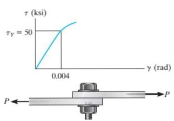
The shear stress-strain diagram for an alloy is shown in the figure. If a bolt having a diameter of 0.25 in. is made of this material and used in the lap joint, determine the modulus of elasticity E and the force P required to cause the material to yield, Take v = 0.3.
Prob. 8-28.
Expert Solution & Answer
Want to see the full answer?
Check out a sample textbook solution
Students have asked these similar questions
The A-36 steel bar consists of two segments, one of a circular cross-section of radius r, and one of square cross-section. If the bar is subjected to the axial loading of P, determine the dimensions of the square segment so that the strain energy within the square segment is the same as in the circular segment.
The bolt has a diameter of 10 mm, and the arm AB has a rectangular cross section that is 12 mm wide by 7 mm thick. Determine the strain energy in the arm due to bending and in the bolt due to axial force. The bolt is tightened so that it has a tension of 500 N. Both members are made of A-36 steel. Neglect the hole in the arm.
The friction pad A is used to support the member,which is subjected to an axial force of P = 2 kN. Thepad is made from a material having a modulus ofelasticity of E = 4 MPa and Poisson’s ratio n = 0.4.If slipping does not occur, determine the normaland shear strains in the pad. The width is 50 mm.Assume that the material is linearly elastic. Also,neglect the effect of the moment acting on the pad.
Chapter 8 Solutions
Statics and Mechanics of Materials, Student Value Edition (5th Edition)
Ch. 8.4 - Define a homogeneous material.Ch. 8.4 - Prob. 2FPCh. 8.4 - Prob. 3FPCh. 8.4 - Prob. 4FPCh. 8.4 - Prob. 5FPCh. 8.4 - As the temperature increases the modulus of...Ch. 8.4 - Prob. 7FPCh. 8.4 - Prob. 8FPCh. 8.4 - Prob. 9FPCh. 8.4 - Prob. 10FP
Ch. 8.4 - The material for the 50-mm-long specimen has the...Ch. 8.4 - If the elongation of wire BC is 0.2 mm after the...Ch. 8.4 - A tension test was performed on a steel specimen...Ch. 8.4 - Data taken from a stressstrain test for a ceramic...Ch. 8.4 - Data taken from a stressstrain test for a ceramic...Ch. 8.4 - Prob. 4PCh. 8.4 - The stress-strain diagram for a steel alloy having...Ch. 8.4 - Prob. 6PCh. 8.4 - The rigid beam is supported by a pin at C and an...Ch. 8.4 - The rigid beam is supported by a pin at C and an...Ch. 8.4 - Prob. 9PCh. 8.4 - The stressstrain diagram for an aluminum alloy...Ch. 8.4 - The stressstrain diagram for an aluminum alloy...Ch. 8.4 - Prob. 12PCh. 8.4 - A bar having a length of 5 in. and cross-sectional...Ch. 8.4 - The rigid pipe is supported by a pin at A and an...Ch. 8.4 - The rigid pipe is supported by a pin at A and an...Ch. 8.4 - Prob. 16PCh. 8.4 - The rigid beam is supported by a pin at C and an...Ch. 8.4 - Prob. 18PCh. 8.4 - Prob. 19PCh. 8.6 - A 100 mm long rod has a diameter of 15 mm. If an...Ch. 8.6 - A solid circular rod that is 600 mm long and 20 mm...Ch. 8.6 - Prob. 15FPCh. 8.6 - Prob. 16FPCh. 8.6 - The acrylic plastic rod is 200 mm long and 15 mm...Ch. 8.6 - The plug has a diameter of 30 mm and fits within a...Ch. 8.6 - The elastic portion of the stress-strain diagram...Ch. 8.6 - The elastic portion of the stress-strain diagram...Ch. 8.6 - The brake pads for a bicycle tire arc made of...Ch. 8.6 - The lap joint is connected together using a 1.25...Ch. 8.6 - The lap joint is connected together using a 1.25...Ch. 8.6 - Prob. 27PCh. 8.6 - The shear stress-strain diagram for an alloy is...Ch. 8.6 - Prob. 29PCh. 8 - The elastic portion of the tension stress-strain...Ch. 8 - Prob. 2RPCh. 8 - Prob. 3RPCh. 8 - Prob. 4RPCh. 8 - Prob. 5RPCh. 8 - Prob. 6RPCh. 8 - The stress-strain diagram for polyethylene, which...Ch. 8 - The pipe with two rigid caps attached to its ends...Ch. 8 - Prob. 9RPCh. 8 - Prob. 10RP
Knowledge Booster


Learn more about
Need a deep-dive on the concept behind this application? Look no further. Learn more about this topic, mechanical-engineering and related others by exploring similar questions and additional content below.Similar questions
- The coupling rod is subjected to a force of 5 kip. Determine the distance d between C and E accounting for the compression of the spring and the deformation of the bolts. When no load is applied the spring is unstretched and d = 10 in. The material is A-36 steel and each bolt has a diameter of 0.25 in. The plates at A, B, and C are rigid and the spring has a stiffness of k = 12 kip>in.arrow_forwardThe pipe with two rigid caps attached to its ends is subjected to an axial force P. If the pipe is made from a material having a modulus of elasticity E and Poisson’s ratio n, determine the change in volume of the material.arrow_forwardThe rod is 200 mm long and 60 mm in diameter. If an axial load of 300 N is applied to it, determine the change in its length, the change in its diameter, normal stress and normal strain. The Poisson's ratio is 0.4 and the modulus of elasticity is 20 GPa.arrow_forward
- The spherical pressure vessel has an inner diameter of 2 m and a thickness of 10 mm. A strain gage having a length of 20 mm is attached to it, and it is observed to increase in length by 0.012 mm when the vessel is pressurized. Determine the pressure causing this deformation, and find the maximum in-plane shear stress, and the absolute maximum shear stress at a point on theouter surface of the vessel. The material is steel, for which Est = 200 GPa and nst = 0.3.arrow_forwardThe rigid lever arm is supported by two A-36 steel wires having the same diameter of 4 mm. If a force of P = 3 kN is applied to the handle, determine the force developed in both wires and their corresponding elongations. Consider A-36 steel as an elastic perfectly plastic material.arrow_forwardThe strain at point A on the pressure-vessel wall has components Px = 480(10-6), Py = 720(10-6), gxy =650(10-6). Determine (a) the principal strains at A, in the x9y plane, (b) the maximum shear strain in the x9y plane, and (c) the absolute maximum shear strain.arrow_forward
- Determine the maximum force P and the corresponding maximum total strain energy stored in the truss without causing any of the members to have permanent deformation. Each member has a cross-sectional area of 2.5(103) mm2 and is made of A-36 steel.arrow_forwardThe 10-mm-diameter bolt is made of an aluminum alloy. It fits through a magnesium sleeve that has an inner diameter of 14 mm and an outer diameter of 22 mm. The original lengths of the bolt and sleeve are 80 mm and 50 mm, respectively. If after the nut on the bolt is tightened the tension in the bolt is 10 kN, determine the change of volume of the bolt and the new length of the sleeve. Wherein both materials behave linearly elastic. Assume the material at A is rigid. E = 70 GPa, Emg = 46 GPa, Ga = 27 GPa, Gmg = 20 GPa.arrow_forwardThe 200 mm long and 20 mm diameter solid circular rod is subjected to an axial force of P. P = 400 and δ = 1.6. ElasticityCalculate the modulus E and the shear modulus G. Take 0.3 Poisson's ratio.arrow_forward
- The pipe is stuck in the ground so that when it is pulled upward the frictional force along its length varies linearly from zero at B to fmax (force/length) at C. Determine the initial force P required to pull the pipe out and the pipe’s elongation just before it starts to slip. The pipe has a length L, cross-sectional area A, and the material from which it is made has a modulus of elasticity E.arrow_forwardDetermine the maximum force P and the corresponding maximum total strain energy that can be stored in the truss without causing any of the members tohave permanent deformation. Each member of the truss has a diameter of 2 in. and is made of A-36 steel.arrow_forwardThe nylon cord has an original length L and is tied to a bolt at A and a roller at B. If a force P is applied to the roller, determine the normal strain in the cord when the roller is at C, and at D. If the cord is originally unstrained when it is at C, determine the normal strain P′ D when the roller moves to D. Show that if the displacements Δ C and Δ D are small, then P′ D = PD − PC.arrow_forward
arrow_back_ios
SEE MORE QUESTIONS
arrow_forward_ios
Recommended textbooks for you
 Elements Of ElectromagneticsMechanical EngineeringISBN:9780190698614Author:Sadiku, Matthew N. O.Publisher:Oxford University Press
 Mechanics of Materials (10th Edition)Mechanical EngineeringISBN:9780134319650Author:Russell C. HibbelerPublisher:PEARSON
 Thermodynamics: An Engineering ApproachMechanical EngineeringISBN:9781259822674Author:Yunus A. Cengel Dr., Michael A. BolesPublisher:McGraw-Hill Education
 Control Systems EngineeringMechanical EngineeringISBN:9781118170519Author:Norman S. NisePublisher:WILEY
 Mechanics of Materials (MindTap Course List)Mechanical EngineeringISBN:9781337093347Author:Barry J. Goodno, James M. GerePublisher:Cengage Learning
 Engineering Mechanics: StaticsMechanical EngineeringISBN:9781118807330Author:James L. Meriam, L. G. Kraige, J. N. BoltonPublisher:WILEY
Elements Of Electromagnetics
Mechanical Engineering
ISBN:9780190698614
Author:Sadiku, Matthew N. O.
Publisher:Oxford University Press
Mechanics of Materials (10th Edition)
Mechanical Engineering
ISBN:9780134319650
Author:Russell C. Hibbeler
Publisher:PEARSON
Thermodynamics: An Engineering Approach
Mechanical Engineering
ISBN:9781259822674
Author:Yunus A. Cengel Dr., Michael A. Boles
Publisher:McGraw-Hill Education
Control Systems Engineering
Mechanical Engineering
ISBN:9781118170519
Author:Norman S. Nise
Publisher:WILEY
Mechanics of Materials (MindTap Course List)
Mechanical Engineering
ISBN:9781337093347
Author:Barry J. Goodno, James M. Gere
Publisher:Cengage Learning
Engineering Mechanics: Statics
Mechanical Engineering
ISBN:9781118807330
Author:James L. Meriam, L. G. Kraige, J. N. Bolton
Publisher:WILEY
EVERYTHING on Axial Loading Normal Stress in 10 MINUTES - Mechanics of Materials; Author: Less Boring Lectures;https://www.youtube.com/watch?v=jQ-fNqZWrNg;License: Standard YouTube License, CC-BY