
Concept explainers
Videos
(a) Assuming the passive sign convention, obtain an expression for the voltage across the 1 Ω resistor in the circuit of Fig. 9.41 which is valid for all t > 0. (b) Determine the settling time of the resistor voltage.
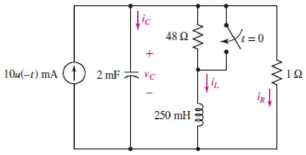
■ FIGURE 9.41
(a)
Obtain an expression for voltage across
Answer to Problem 15E
The expression for voltage across
Explanation of Solution
Formula used:
The expression for the exponential damping coefficient or the neper frequency is as follows:
Here,
The expression for the resonating frequency is as follows:
Here,
The expression for the two solutions of the characteristic equation of a parallel
Here,
The expression for the natural response of the parallel
Here,
Calculation:
The redrawn circuit diagram is given in Figure 1 for
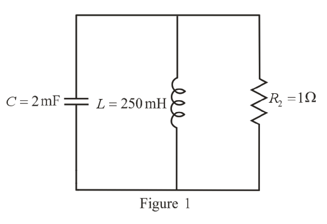
Refer to the redrawn Figure 1:
Substitute
Substitute
As value of neper frequency
Substitute
Substitute
The unit-step forcing function as a function of time which is zero for all values of its argument less than zero and which is unity for all positive values of its argument.
Here,
So, at
The capacitor and the inductor are connected in the circuit for long time.
So, the capacitor behaves as open circuit and the inductor behaves as short circuit.
The redrawn circuit diagram is given in Figure 2 for
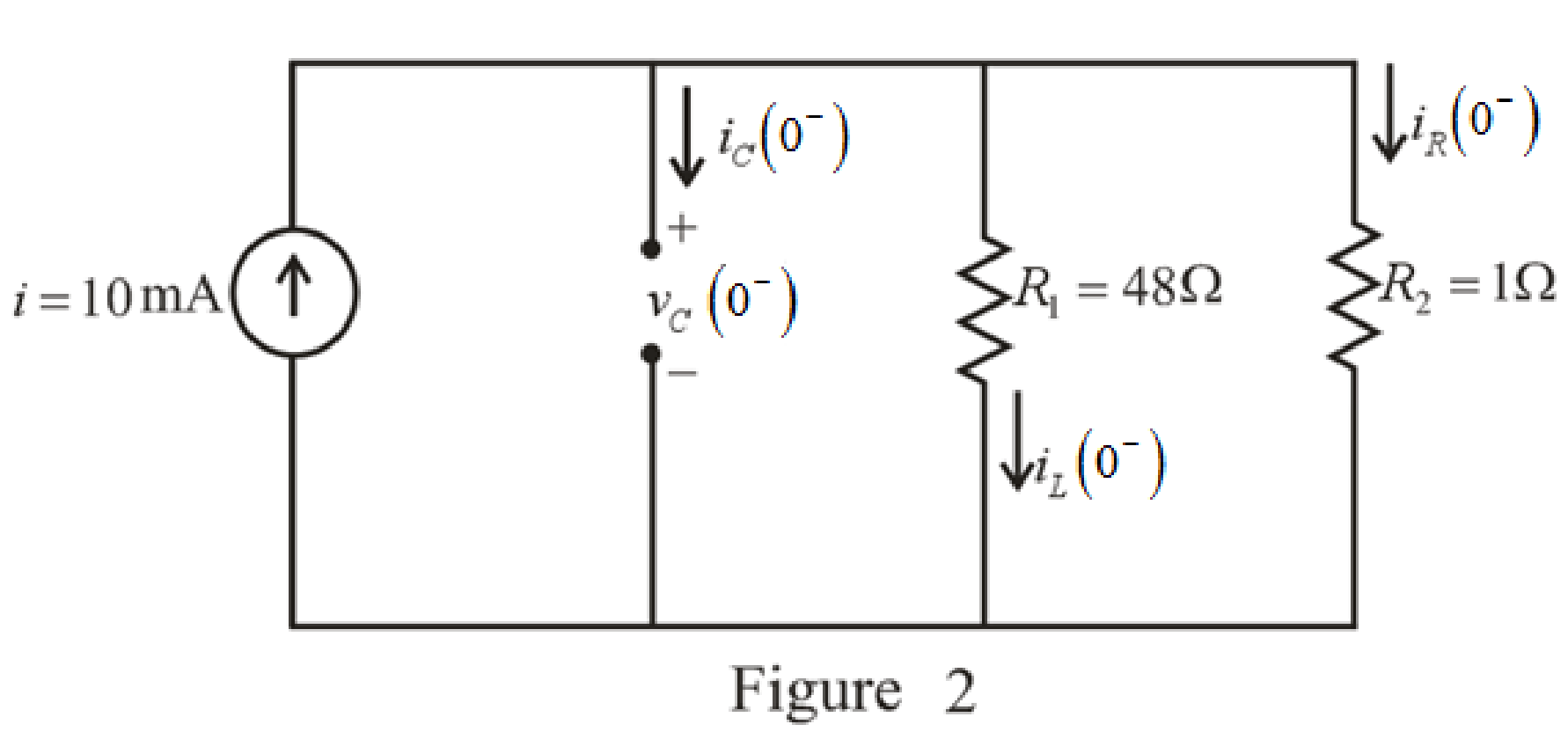
Refer to the redrawn Figure 2:
The expression for the current flowing in the
Here,
Substitute
The expression for the voltage across the
Here,
Substitute
The switch closes at
The capacitor does not allow sudden change in the voltage and the capacitor does not allow sudden change in the current.
So,
As parallel branches have same voltage across them, so, voltage across resistor
Therefore,
The redrawn circuit diagram is given in Figure 3 for
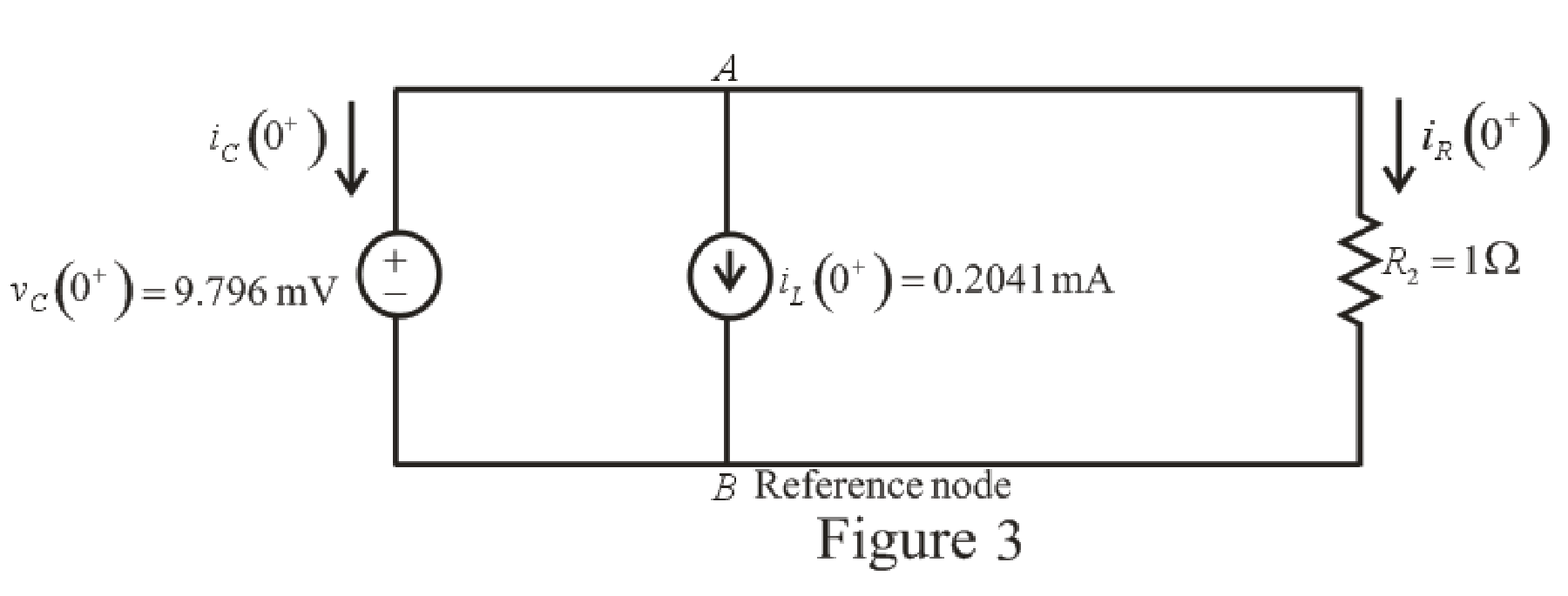
Refer to the redrawn Figure 3:
The expression for the current flowing in the resistor
Here,
Substitute
Apply KCL at node
Here,
Substitute
Rearrange for
Substitute
Substitute
The voltage across the resistor
Substitute
Rearrange for
The expression for the current flowing through the
Substitute
Rearrange for
Substitute
The current flowing through the
Substitute
Rearrange for
Substitute
Rearrange for
Substitute
Substitute
Conclusion:
Thus, expression for voltage across
(b)
Find settling time of the resistor voltage.
Answer to Problem 15E
The settling time is
Explanation of Solution
Calculation:
Function for voltage across resistor
The maximum value of voltage
Substitute
So, the maximum value of voltage
Settling time is the time at which the value of the voltage
The expression for the voltage
Here,
Substitute
Substitute
Since the component
So, the new equation is:
Rearrange equation (20).
Take natural logarithm both sides.
Conclusion:
Thus, the settling time is
Want to see more full solutions like this?
Chapter 9 Solutions
ENGINEERING CIRCUIT...(LL)>CUSTOM PKG.<


- For the circuit.( Need only handwritten solution please otherwise downvote)arrow_forwardHi im struggling to understand how you would sketch DC component Va and AC component va for the following questions. Could you show me how on both questions so i understand how to do it on different scenarios. thank you.Also is there like a universal formula i can use as every graph is not the same. Also can u show how to identify the period of each graph.arrow_forwardThe natural response is the behavior of a circuit for a long time when an external excitation is applied. True Falsearrow_forward
- 1- a- Find Leg and Ceq at the terminals of the circuits, Note: Unit od capactors are mF, Unit of inductors are H. 3mf 3+4 L Loq=?arrow_forwardb) Find the Node voltage at point “a". Give the answer as a function of time Va(t)= ? Note: Be careful about the terminal signs. (10p) O 20cos ( 100t) V A 10 sin (100tt!s@) V -5tj2 V O - 10 (36° Varrow_forward%AO O ".ll Asiacell|ASIACELL Electrical Engineering Que.. www.bartleby.com m m Q&A Sign in Engineering / Electrical Engineeri... / Q&A Libr... I- Electrical Engineering Question Standard Chartered S The switch in the circuit shown has been closed for a long time. At t 0, the switch is opened. Find the final value of Vc? 100 20 2 1=0 I mA ( 2 mF 30 N 15 0 ful Expert Answer This question hasn't been answered yet. •••arrow_forward
- 2s. IX. Refer to Figure 9. Switch Si in the circuit below is closed at t=0, and switch S2 is closed at t = 1. Find i(t) for all t. 2. Find i(1) and i(5).arrow_forwardHai kindly helparrow_forwardThe ac bridge shown in Fig. 9.84 is known as a Maxwell bridge and is used for accurate measurement of inductance and resistance of a coil in terms of a standard capacitance C.. Show that when the bridge is balanced, R2 R3 R₁ Lx = R₂R3Cs and Rx = 1.6 ΚΩ, Find Lx and R, for R₁ = 40 kN, R₂ R3 = 4 kn, and C₂ = 0.45 µF. R₁ R3 Cs R₂ AC meter R₂ ellarrow_forward
- - 11 The pathway for a binary electrical signal between gates in an integrated circuit can be modeled as an RC circuit, as shown in the figure to the right; the voltage source models the transmitting gate, and the capacitor models the receiving gate. Suppose the resistance is 300 $2 and the capacitance is 10 F (10 picofarads, pF). If the capacitor is initially uncharged and the transmitting gate changes instantaneously from 0 to 3 V, how long will it take for the voltage at the receiving gate to reach 2 V? It will take seconds. (Use scientific notation. Round to three decimal places as needed.) (…) R www ~Earrow_forwardPlease provide a clear solution and please answer within 30 minutes! Kindly follow the instructions, thank you! Use stored values to lessen round-off errors Maintain your answers to 4 decimal places Final answers must only contain numerical values(including the sign). Units are usually already defined in the problem. (If not, input your answers in the base unit)arrow_forwardAt time t=0 the switch is clsoed and DC voltage Vi(t) is applied as input and Vo(t) is the voltage across the inductor and the capacitor. Using this information, find the possible general solutions for Vo(t). This includes finding general solutions based on the nature of the poles of this system. 1. **Overdamped (Distinct Real Poles):** Vo(t)\=A1eλ1t+A2eλ2tV\_o(t) = A\_1 e^{\\lambda\_1 t} + A\_2 e^{\\lambda\_2 t}Vo(t)\=A1eλ1t+A2eλ2t where λ1\\lambda\_1λ1 and λ2\\lambda\_2λ2 are the distinct real poles. 2. **Critically Damped (Repeated Real Poles):** Vo(t)\=(A1+A2t)eλtV\_o(t) = (A\_1 + A\_2 t) e^{\\lambda t}Vo(t)\=(A1+A2t)eλt where λ\\lambdaλ is the repeated real pole. 3. **Underdamped (Complex Conjugate Poles):** Vo(t)\=e−ζωnt(A1cos(ωdt)+A2sin(ωdt))V\_o(t) = e^{-\\zeta \\omega\_n t} (A\_1 \\cos(\\omega\_d t) + A\_2 \\sin(\\omega\_d t))Vo(t)\=e−ζωnt(A1cos(ωdt)+A2sin(ωdt)) where: * ωn\=1LC\\omega\_n = \\frac{1}{\\sqrt{LC}}ωn\=LC1 is the natural…arrow_forward
 Introductory Circuit Analysis (13th Edition)Electrical EngineeringISBN:9780133923605Author:Robert L. BoylestadPublisher:PEARSON
 Delmar's Standard Textbook Of ElectricityElectrical EngineeringISBN:9781337900348Author:Stephen L. HermanPublisher:Cengage Learning
 Programmable Logic ControllersElectrical EngineeringISBN:9780073373843Author:Frank D. PetruzellaPublisher:McGraw-Hill Education
 Fundamentals of Electric CircuitsElectrical EngineeringISBN:9780078028229Author:Charles K Alexander, Matthew SadikuPublisher:McGraw-Hill Education
 Electric Circuits. (11th Edition)Electrical EngineeringISBN:9780134746968Author:James W. Nilsson, Susan RiedelPublisher:PEARSON
 Engineering ElectromagneticsElectrical EngineeringISBN:9780078028151Author:Hayt, William H. (william Hart), Jr, BUCK, John A.Publisher:Mcgraw-hill Education,