
Concept explainers
Videos
For the circuit represented by Fig. 9.44, the two resistor values are R1 = 0.752 Ω and R2 = 1.268 Ω, respectively. (a) Obtain an expression for the energy stored in the capacitor, valid for all t > 0; (b) determine the settling time of the current labeled iA.
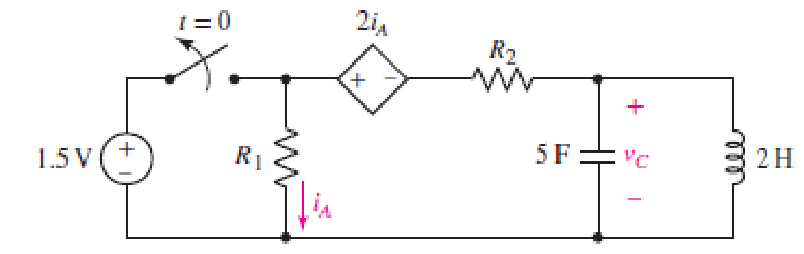
FIGURE 9.44
(a)
Find the expression for the energy stored in the capacitor, valid for all
Answer to Problem 20E
The expression for the energy stored in the capacitor, valid for all
Explanation of Solution
Given Data:
The value of the resistor
Formula used:
The expression for the exponential damping coefficient or the neper frequency is as follows:
Here,
The expression for the resonating frequency is as follows:
Here,
The expression for the two solutions of the characteristic equation of a parallel
Here,
The expression for the natural response of the parallel
Here,
The expression for the energy stored in the capacitor is as follows:
Here,
Calculation:
The capacitor and the inductor are connected in the circuit for long time.
So, the capacitor behaves as open circuit and the inductor behaves as short circuit.
The redrawn circuit diagram is given in Figure 1 for
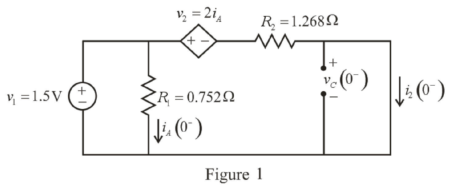
Refer to the redrawn Figure 1:
As parallel branches have same voltage so voltage across
The expression for the current flowing through
Here,
Substitute
The expression for the current flowing through the
Here,
Substitute
Substitute
As parallel branches have same voltage and the voltage across the short circuit branch has
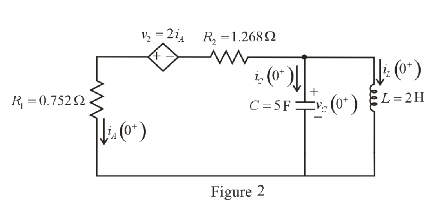
The capacitor does not allow sudden change in the voltage and the inductor does not allow sudden change in current.
So,
Therefore, the voltage across the
The redrawn circuit diagram is given in Figure 2 at
 l
l
Refer to the redrawn Figure 2:
As the voltage across the he
To find equivalent resistance across the capacitor, a
The redrawn circuit diagram is given in Figure 3.
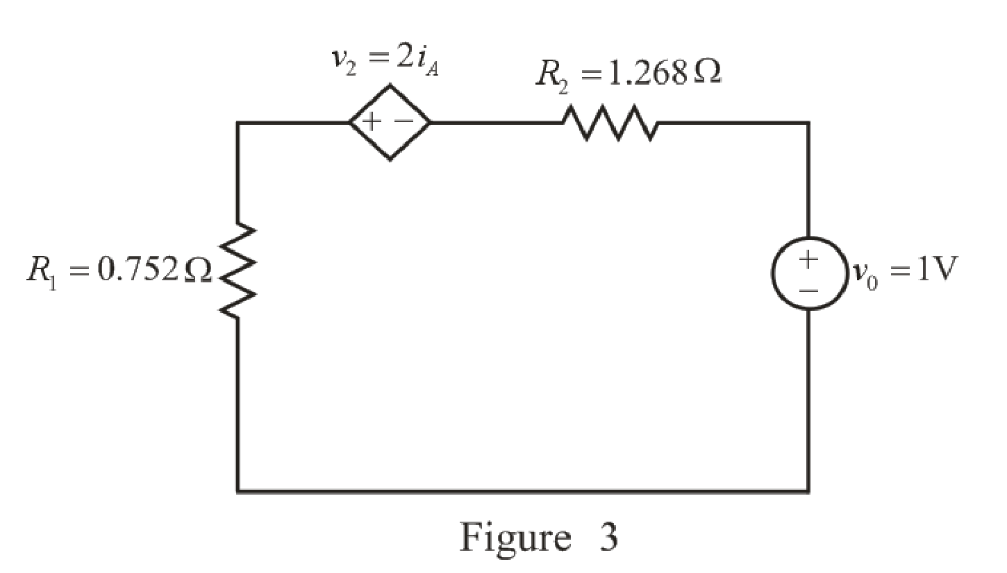
Refer to the redrawn Figure 3:
Apply KVL in the circuit.
Here,
Substitute
Rearrange for
The expression for the equivalent resistance the circuit is as follows:
Here,
Substitute
Substitute
Substitute
Here, the exponential damping coefficient is greater than the resonating frequency,
So, the response of the parallel
Substitute
Substitute
Substitute
Substitute
The voltage across the capacitor at
Substitute
Rearrange for
The expression for the current flowing through the
Substitute
Rearrange for
Substitute
The current flowing through the
Substitute
Rearrange for
Substitute
Rearrange for
Substitute
Substitute
Substitute
So, the energy stored in the capacitor, valid for all
Conclusion:
Thus, the expression for the energy stored in the capacitor, valid for all
(b)
Find the settling time of the current
Answer to Problem 20E
The settling time of current
Explanation of Solution
Calculation:
The redrawn circuit diagram is given in Figure 4.
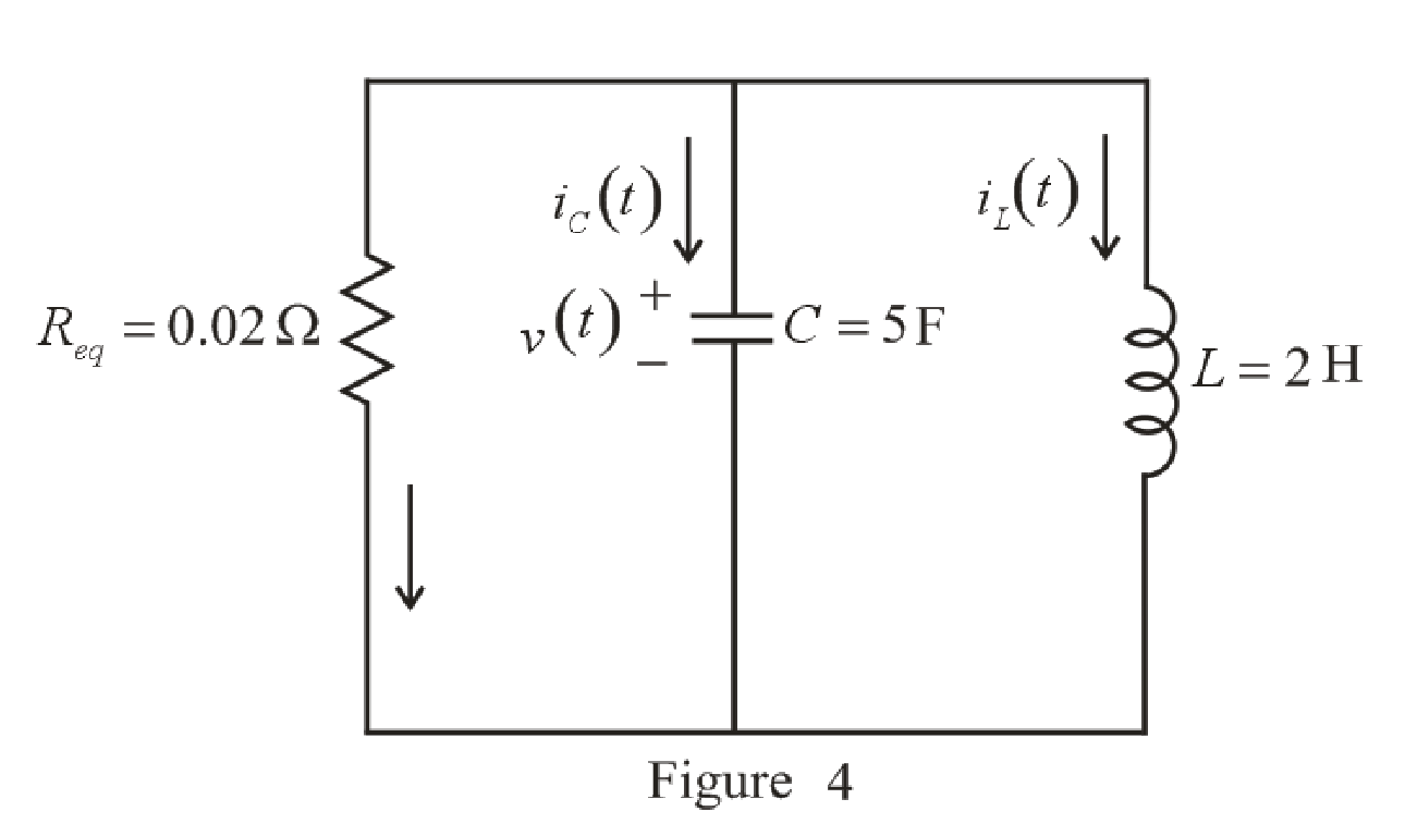
Refer to the redrawn Figure 4:
The expression for the current flowing in the left hand mesh at
Here,
Substitute
Differentiate both side of the equation (19).
The maximum value is obtained when derivative is equated to zero.
Rearrange equation (20).
Take natural logarithm both sides.
Rearrange for
Substitute
So, the value of the maximum current flowing in the left hand mesh is
Settling time is the time at which the value of the current reaches
The expression for the current at
Here,
Substitute
The value of current flowing in the left hand mesh at
Substitute
Since the component
So, the new equation is:
Rearrange equation (22).
Take natural logarithm both sides.
Rearrange for
So, the settling time of the currentflowing in the left hand mesh
Conclusion:
Thus, the settling time of current
Want to see more full solutions like this?
Chapter 9 Solutions
ENGINEERING CIRCUIT...(LL)>CUSTOM PKG.<


- Need help it’s urgentarrow_forwardUnit Step Functionarrow_forwardWrite the circuit current equation, the capacitor voltage equation and the voltage equation at the end of R1 for the period from the beginning of this period (t = 0) when the K switch is in the 1 position until the K switch is in the 2 position.arrow_forward
- For the circuit in Figure 3 the switch is in the left position for several minutes: (a) Find the Initlal voltage, V, on the capacitor just before the switch is flipped (b) Find an expression v(t) that describes the voltage across the 20 N resistor after the switch has been Figure 3 U 09 flipped to the right NOTE: Remember what we said in class: use a Circuit-Specific Equation to get a value you know. Then solve for whatever else the problem asks for +50 µF 380 0 20 2arrow_forwardElectrical Engineering 9. Find the solution to the linear constant coeffcient difference equation (n)= >(n=1)-y(n-2)+ 2u(n) with (-1)=2 and y(-2)=1.arrow_forwardGiven That: Is=0.0098, R1=60000, R2=6000 0, L=16 H, C=2 F, The circuit shown below under dc conditions find the following: L ell Is R1 R2 the current in L The voltage across capacitorarrow_forward
- You are investigating the electrical testing circuits and find that, in an inductive circuit, the relationship between instantaneous current i (amps) and the time t (secs) is given by: i = 2.1(1-e-9t) You have been asked to determine the time taken for the current to rise from 1 to 1.5 amps. Comment on the time taken for the current to rise the same increment from 1.5 to 2 amps and give reasons.arrow_forwardPlease help me with parts a, b, c, and darrow_forwardPart (0) Prior to coming to the lab, calculate the theoretical parameter values of S₁, S2, a, wd and T (time period) for the RLC circuit shown in Figure 9.1 and record them in Table 9.1 + 2Vp-p ( Figure 9.1: Series RLC Circuit α Rtot 2009 m Wo 100mH Table 9.1: Theoretical Parameter Values of Figure 9.1 Parameter Calculated Value Wd S₁ S₂ T 39 0.01μFarrow_forward
- I would like to understand better the steps that go into before and in the plotting to relate the concepts better.arrow_forwardThe circuit of Fig. 9.2 is modified substantially, with the resistor being re- placed with a 1 k resistor, the inductor swapped out for a smaller 7 mH ver- sion, the capacitor replaced with a 1 nF alternative, and now the inductor is ini- tially discharged while the capacitor is storing 7.2 mJ. (a) Compute a, wo, $1, and $2, and verify that the circuit is still overdamped. (b) Obtain an expression for the current flowing through the resistor which is valid for t > 0. (c) Calcu- late the magnitude of the resistor current at t = 10 µs. 6Ω 7 H v FIGURE 9.2 A parallel RLC circuit used as a numer- ical example. The circuit is overdamped.arrow_forward7. The voltage across a 22 u F capacitor is shown in Figure 9 below. 15 10 2 4 t(ms) Figure 9 (a) State the relationship between the voltage and the current of the capacitor. (b) Sketch the waveform for the current in the capacitor. (c) Determine the energy stored in the capacitor at t = 6 ms.arrow_forward
 Introductory Circuit Analysis (13th Edition)Electrical EngineeringISBN:9780133923605Author:Robert L. BoylestadPublisher:PEARSON
 Delmar's Standard Textbook Of ElectricityElectrical EngineeringISBN:9781337900348Author:Stephen L. HermanPublisher:Cengage Learning
 Programmable Logic ControllersElectrical EngineeringISBN:9780073373843Author:Frank D. PetruzellaPublisher:McGraw-Hill Education
 Fundamentals of Electric CircuitsElectrical EngineeringISBN:9780078028229Author:Charles K Alexander, Matthew SadikuPublisher:McGraw-Hill Education
 Electric Circuits. (11th Edition)Electrical EngineeringISBN:9780134746968Author:James W. Nilsson, Susan RiedelPublisher:PEARSON
 Engineering ElectromagneticsElectrical EngineeringISBN:9780078028151Author:Hayt, William H. (william Hart), Jr, BUCK, John A.Publisher:Mcgraw-hill Education,