
Videos
Consider the circuit depicted in Fig. 9.40. (a) Obtain an expression for iL(t) valid for all t > 0. (b) Obtain an expression for iR(t) valid for all t > 0. (c) Determine the settling time for both iL and iR.
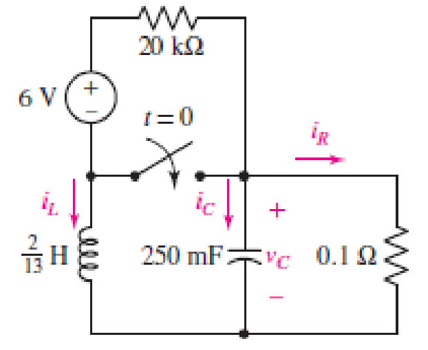
■ FIGURE 9.40
(a)
Obtain an expression for
Answer to Problem 13E
The current across inductor
Explanation of Solution
Formula used:
The expression for the exponential damping coefficient in parallel
Here,
The expression for the resonating frequency in parallel
Here,
The expression for the two solutions of the characteristic equation of a parallel
Here,
The expression for the natural response of the parallel
Here,
Calculation:
The redrawn circuit is shown in Figure 1 as follows:
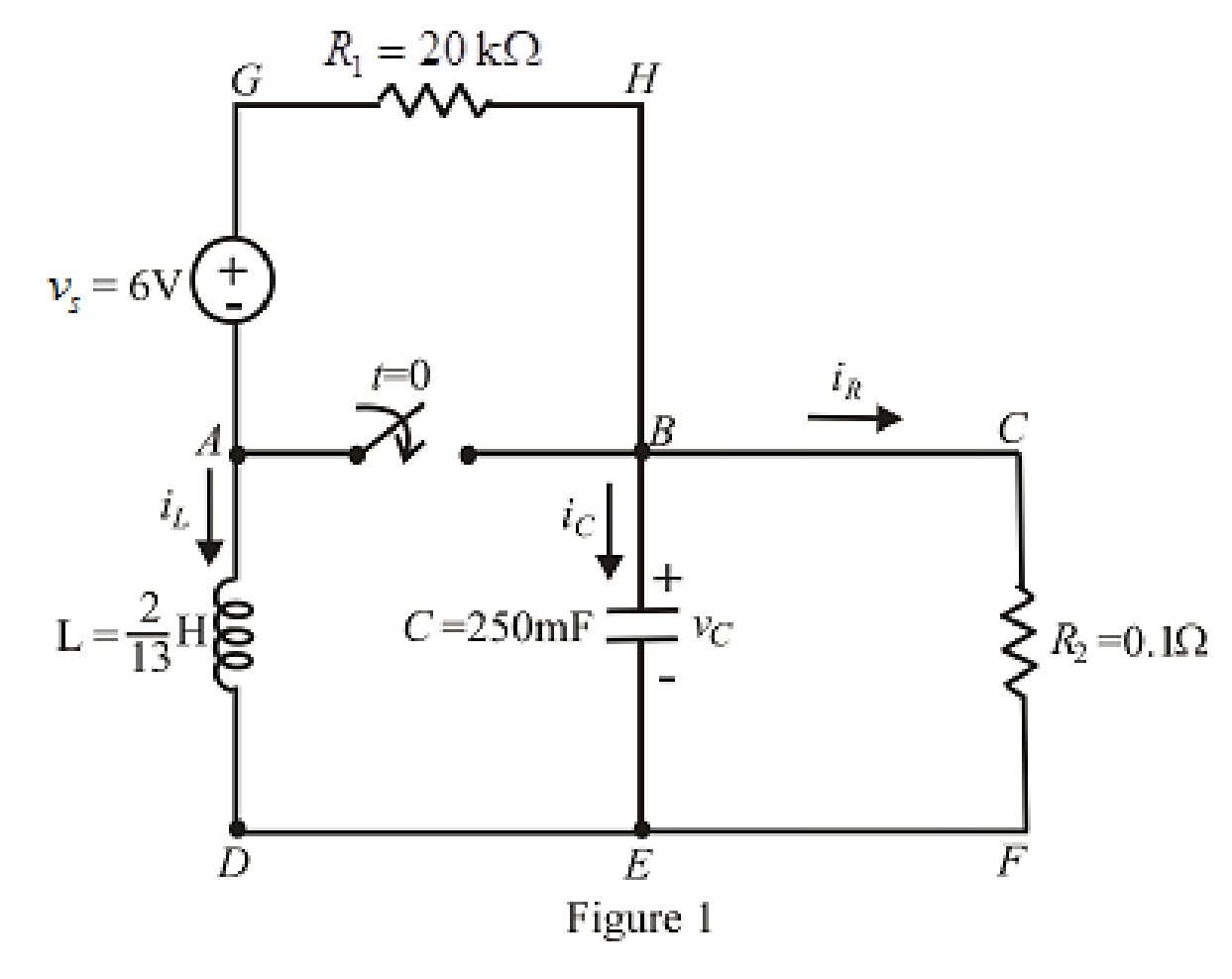
Refer to the Figure 1:
At
Here,
The redrawn circuit at
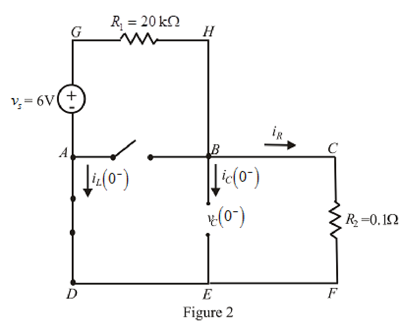
Refer to the Figure 2:
Substitute
The expression for voltage
Here,
Substitute
Substitute
Rearrange for
At
The voltage across inductor is same as voltage across capacitor due to parallel circuit and thus, the expression for voltage across inductor is:
The redrawn circuit is shown in Figure 3 as follows:
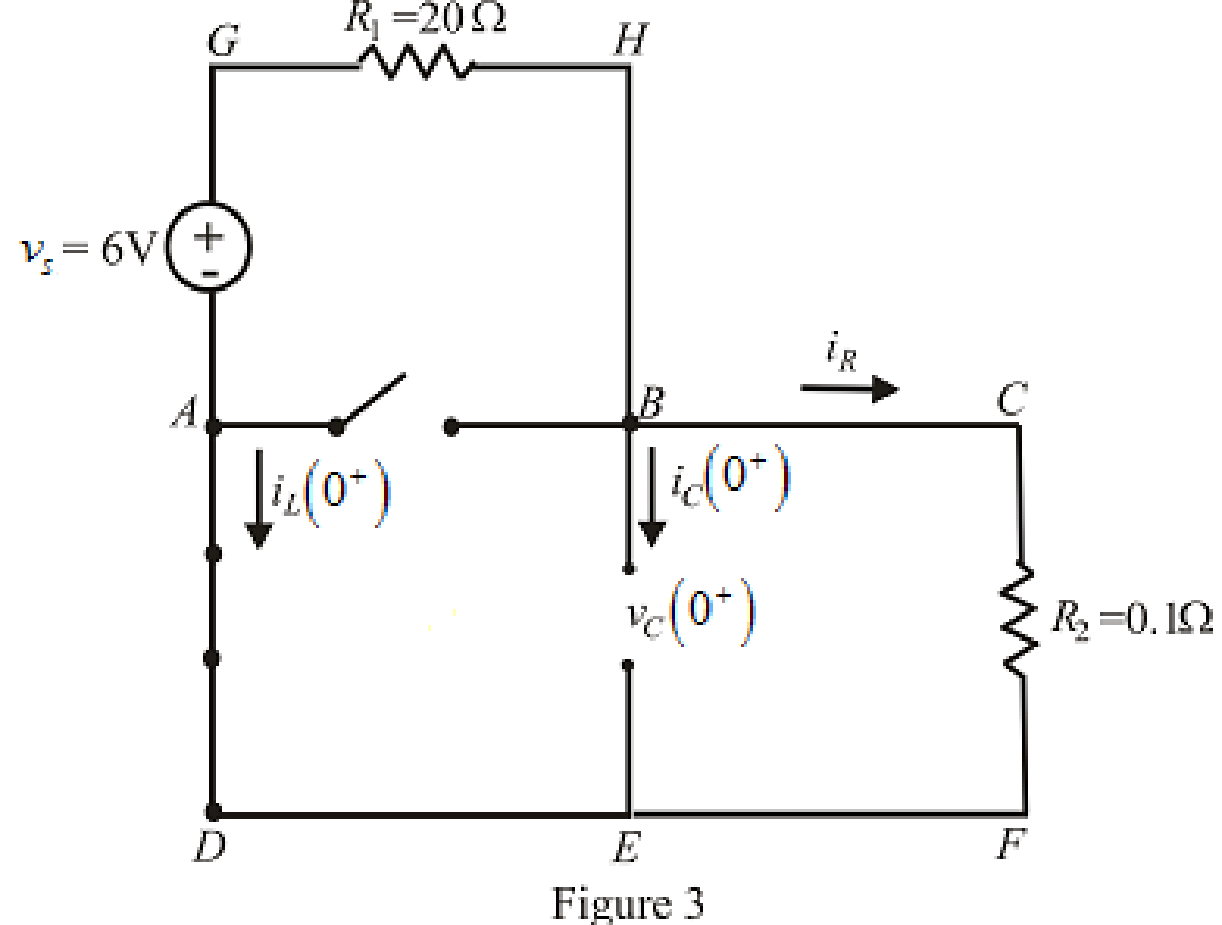
Refer to the Figure 3:
Substitute
Substitute
Differentiate equation (5) both the sides with respect to time
The expression for the voltage across inductor at time
At
Substitute
Rearrange for
Substitute
At
The circuit diagram is redrawn as shown in Figure 4 for
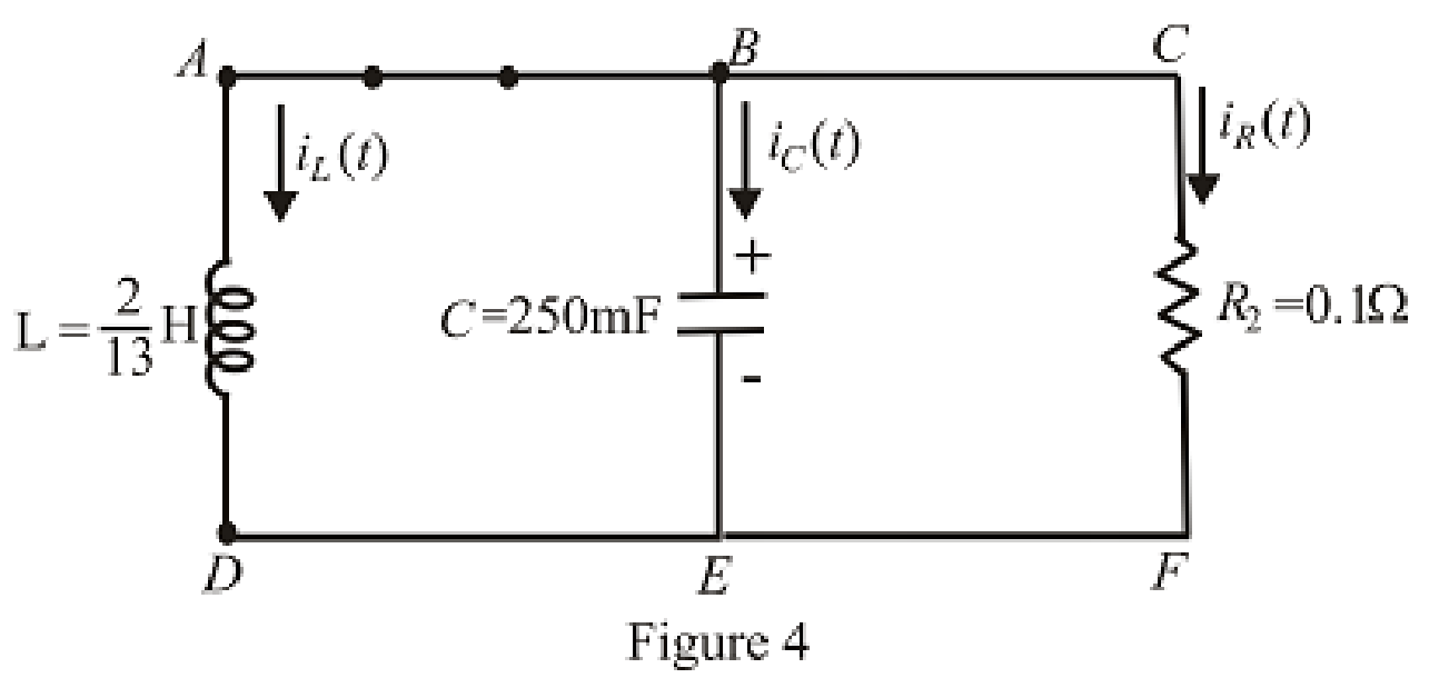
Refer to the redrawn Figure 4:
Substitute
Substitute
As value of exponential frequency
Substitute
Substitute
Substitute
Substitute
Solve for
Rearrange for
Substitute
Rearrange for
Substitute
Conclusion:
Thus, the current across inductor
(b)
Find the equation for current across resistor for
Answer to Problem 13E
The equation of current
Explanation of Solution
Calculation:
Refer to the Figure 3:
The expression for current across resistor at
At
Therefore,
At
Substitute
At
Substitute
Conclusion:
Thus, the equation of current
(c)
Find the settling time for both
Answer to Problem 13E
The settling time for
Explanation of Solution
Calculation:
The settling time is the time at which current reaches to
Since the inductor current is exponential in nature and time cannot be taken as negative, therefore, inductor current takes its maximum value at
Substitute
The maximum value of current is:
The expression for current at settling time
Substitute
The settling time is the time at which the current is decreased to
Equation (24) is solved by scientific calculator which can determine the value of time
Take log both the side in equation (25).
Rearrange for
Substitute
The maximum value of current is:
The expression for current at settling time
Substitute
The settling time is the time at which the current is decreased to
The equation can be approximated for
Take log both the sides of equation (28).
Rearrange for
Conclusion:
Thus, the settling time for
Want to see more full solutions like this?
Chapter 9 Solutions
ENGINEERING CIRCUIT...(LL)>CUSTOM PKG.<


- Consider the following circuit, select the correct statement(s) below.. D Λ D Q x3 Clock 0 Q The shortest clock duration is determined by TcQ_min +su +TOR- The shortest clock duration is determined by TCQ_max +tu+TOR The shortest clock duration is determined by TcQ_max +tu+TAND We don't need to worry about the hold time requirement th.arrow_forward- 11 The pathway for a binary electrical signal between gates in an integrated circuit can be modeled as an RC circuit, as shown in the figure to the right; the voltage source models the transmitting gate, and the capacitor models the receiving gate. Suppose the resistance is 300 $2 and the capacitance is 10 F (10 picofarads, pF). If the capacitor is initially uncharged and the transmitting gate changes instantaneously from 0 to 3 V, how long will it take for the voltage at the receiving gate to reach 2 V? It will take seconds. (Use scientific notation. Round to three decimal places as needed.) (…) R www ~Earrow_forwardThe following signal is a) odd and b) even Find its components, formula and chart show with. f(t)arrow_forward
- 9.pdf - Adobe Acrobat Reader DC (64-bit) ndow Help FINAL EP QP_SEM . x Sign In 10 / 12 116% Search Combine PDF Export PDF A capacitor is charged with 50 mC in a time of 20 uS. If the energy stored in the capacitor is 5 J, Edit PDF find (i) voltage across the capacitor, (ii) current through the capacitor and (iii) value of capacitance. Create PDF EComment Combine Files E0 Organize Pag Delete, insert, extract and rotate pages. Try now Convert, edit and e-sign Parrow_forwardKindly determine the Norton equivalent of this figure as seen by RL. Please do provide an explanation. Thank you.arrow_forward1. The following questions concern plotting of signals. (a) Find the equation: Note the signal keeps continuing to the right off the graph as it is right before t = 6. (b) Find the equation: Note: The curved part between 2 and 4 seconds is a form of a cosine function.arrow_forward
- Example 8: For the system x -+- of the following statement about the system is true? (A) Controllable and stable (B) Uncontrollable and stable (C) Controllable and unstable (D) Uncontrollable and unstable Solution: (D) #, whicharrow_forwardPhotos - 265121502 2337735863035096_3568501418110557974_n.png 106% A See all photos + Add to 女 & Edit & Create v 12 Share ... Problem #2: Assume that the circuit has been connected for a very long time. (Note: x = 2 (a) As time approaches infinity, what will happen to the capacitor and inductor? (b) From your answer in (a), draw the equivalent circuit (label appropriately) (c) From your circuit in (b), determine the "steady-state" or "final" values of vc, ic , iL and v. 10 A 4 kΩ 5 kN ļic 3 µF 1 kN 2 kN 4 nH Maximum size for new files: 10Marrow_forwardT = tc + td = 0.693R1C1 +0.693R2C1 = 0.693(R1 + R2)C1.......(1) f = 1 T = 1/(tc + td) . ..(2) Using equation (1) (or 2) to find the values for R1 and R2. Use C1 = 9.4 nF and C = 1uF. A. Design a pulse generator for frequencies = 15 KHz, 10 KHz and 5 KHz with a 70% duty cycle. B. For frequency = 200 Hz, generate the waveform for the following duty cycles: 90%, 70%, 50%, 30%, and 10%. Vcc Icharge = lcc R₁ www Reset 4 Discharge Idischarge Threshold 6 Trigger 2 Control S www 8 Vcc R S RST 0 Out 3 Q' 1 Ground Figure 1: Modified oscillator based on 555 Timer IC.arrow_forward
- Circuits Lab Simulation | Schoc x 6 https://iti-submission-google.a x -> A ti-submission-google.app.schoology.com/assignment/student/59013660 I Netflix M maaoun4@hawkm.. HFC Current Students.. Home | Schoology M Inbox (2,780) - 20. Q Student Portal D DocHul ps Course: Student R.. Maya Aoun - Circuits Lab Simulation - 10382745 * O File Edit View Insert Format Tools Add-ons Help Last edit was made 8 minutes ago by Zainab Chebib Comic San. B IU A CD 田回▼ E - E 100% Normal text 12 2 3 4 . I .S 6 .I 7 4. r in Tne Dianks Dasea on Tne Two measuring aevices beiow. Voltmeter Ammeter a. A voltmeter is a device that measures b. An ammeter is a device that measures Part B: A Simple Circuit 5. First, start by building a simple circuit using a battery, switch, connecting wires and one light bulb. 6. Based on the circuit you built in the last question, figure #_ representation of a simple circuit. is the correct picture 3 7. Fill in the blanks using the switch feature of the circuit. a. When the…arrow_forwardH = 3RM2cos(9ft) where f = frequency, t = time, and the remaining variables are either proportionality constants or material constants. What is the maximum value H could have (algebraic answer)arrow_forwardElectrical Engineering (a) Some polycrystalline photovoltaic cells are to be arranged to provide an output of 12V and a power of 120W. Design and sketch out the cell configuration that meets the specification, using a sketch. The datasheet shows that open-circuit voltage is 0.622V, short-circuit current is 8.XY A, and fill factor is 0.7Z. X=3 Y=2 Z=2arrow_forward
 Introductory Circuit Analysis (13th Edition)Electrical EngineeringISBN:9780133923605Author:Robert L. BoylestadPublisher:PEARSON
 Delmar's Standard Textbook Of ElectricityElectrical EngineeringISBN:9781337900348Author:Stephen L. HermanPublisher:Cengage Learning
 Programmable Logic ControllersElectrical EngineeringISBN:9780073373843Author:Frank D. PetruzellaPublisher:McGraw-Hill Education
 Fundamentals of Electric CircuitsElectrical EngineeringISBN:9780078028229Author:Charles K Alexander, Matthew SadikuPublisher:McGraw-Hill Education
 Electric Circuits. (11th Edition)Electrical EngineeringISBN:9780134746968Author:James W. Nilsson, Susan RiedelPublisher:PEARSON
 Engineering ElectromagneticsElectrical EngineeringISBN:9780078028151Author:Hayt, William H. (william Hart), Jr, BUCK, John A.Publisher:Mcgraw-hill Education,