
SHIGLEY'S MECH.ENGIN....(LOOSE)>CUSTOM<
10th Edition
ISBN: 9781260163155
Author: BUDYNAS
Publisher: MCG CUSTOM
expand_more
expand_more
format_list_bulleted
Videos
Textbook Question
Chapter 9, Problem 4P
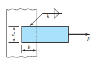
9–1 to 9–4 The figure shows a horizontal steel bar of thickness h loaded in steady tension and welded to a vertical support. Find the load F that will cause an allowable shear stress, τallow, in the throats of the welds.
| Problem Number | b | d | h | τallow |
| 9–1 | 50 mm | 50 mm | 5 mm | 140 Mpa |
| 9–2 | 2 in | 2 in |
|
25 kspi |
| 9–3 | 50 mm | 30 mm | 5 mm | 140 Mpa |
| 9–4 | 4 in | 2 in |
|
25 kpsi |
Expert Solution & Answer
Want to see the full answer?
Check out a sample textbook solution
Students have asked these similar questions
The figure shows a solid 2-inch diameter roller that is attached to the wall by means of a permanent clamping. Specify the weld size for the case where the maximum allowable shear stress is 18 kpsi.
appropriate length of the weld joint shown in the figure if the force is equal to (60000lb) and the operating stress value is (60ksi) and the size of the weld is (1/4in).
A 1/4 in fillet weld is to transmit a total force of 12,000 lb. If the allowable unit stress in shear on the weld is 15,800 psi, the minimum effective length of the weld must be A. 5.4 B 4.9 in C. 4.3 in D 3.9 in.
Chapter 9 Solutions
SHIGLEY'S MECH.ENGIN....(LOOSE)>CUSTOM<
Ch. 9 - 91 to 94 The figure shows a horizontal steel bar...Ch. 9 - 91 to 94 The figure shows a horizontal steel bar...Ch. 9 - 91 to 94 The figure shows a horizontal steel bar...Ch. 9 - 91 to 94 The figure shows a horizontal steel bar...Ch. 9 - 95 to 98 For the weldments of Probs. 91 to 94, the...Ch. 9 - 95 to 98 For the weldments of Probs. 91 to 94, the...Ch. 9 - 95 to 98 For the weldments of Probs. 91 to 94, the...Ch. 9 - 95 to 98 For the weldments of Probs. 91 to 94, the...Ch. 9 - 99 to 912 The materials for the members being...Ch. 9 - Prob. 10P
Ch. 9 - Prob. 11PCh. 9 - 99 to 912 The materials for the members being...Ch. 9 - 913 to 916 A steel bar of thickness h is welded to...Ch. 9 - 913 to 916 A steel bar of thickness h is welded to...Ch. 9 - 913 to 916 A steel bar of thickness h is welded to...Ch. 9 - Prob. 16PCh. 9 - Prob. 17PCh. 9 - 917 to 920 A steel bar of thickness h, to be used...Ch. 9 - 917 to 920 A steel bar of thickness h, to be used...Ch. 9 - 917 to 920 A steel bar of thickness h, to be used...Ch. 9 - Prob. 21PCh. 9 - 921 to 924 The figure shows a weldment just like...Ch. 9 - Prob. 23PCh. 9 - Prob. 24PCh. 9 - 9-25 to 9-28 The weldment shown in the figure is...Ch. 9 - 9-25 to 9-28 The weldment shown in the figure is...Ch. 9 - Prob. 27PCh. 9 - 925 to 928 The weldment shown in the figure is...Ch. 9 - The permissible shear stress for the weldment...Ch. 9 - Prob. 30PCh. 9 - 9-30 to 9-31 A steel bar of thickness h is...Ch. 9 - In the design of weldments in torsion it is...Ch. 9 - Prob. 33PCh. 9 - Prob. 34PCh. 9 - The attachment shown carries a static bending load...Ch. 9 - The attachment in Prob. 935 has not had its length...Ch. 9 - Prob. 37PCh. 9 - Prob. 39PCh. 9 - Prob. 40PCh. 9 - Prob. 42PCh. 9 - 9-43 to 9-45 A 2-in dia. steel bar is subjected to...Ch. 9 - 9-43 to 9-45 A 2-in dia. steel bar is subjected to...Ch. 9 - Prob. 45PCh. 9 - Prob. 46PCh. 9 - Find the maximum shear stress in the throat of the...Ch. 9 - The figure shows a welded steel bracket loaded by...Ch. 9 - Prob. 49PCh. 9 - Prob. 50PCh. 9 - Prob. 51PCh. 9 - Brackets, such as the one shown, are used in...Ch. 9 - For the sake of perspective it is always useful to...Ch. 9 - Hardware stores often sell plastic hooks that can...Ch. 9 - For a balanced double-lap joint cured at room...
Knowledge Booster


Learn more about
Need a deep-dive on the concept behind this application? Look no further. Learn more about this topic, mechanical-engineering and related others by exploring similar questions and additional content below.Similar questions
- All-round fillet weld with a steel beam weld thickness a=6 mm and weld seam length shown in the figure welded to the steel column. Forces of 2 kN and 3 kN from the beam end in the horizontal and vertical directions, respectively has been applied. The smallest yield strength of the weld material so that the steel structure has a safety of 2.5. Calculate according to von Mises static damage theory ?arrow_forwardThe arm in the figure is combined with a rod with a diameter of d=30 mm and a neck (corner) weld of a=5 mm thickness to the rod wall sourced with. The force acting on the arm is F=2 kN. The lengths are L1=L2=100 mm. Joined parts St37-2 (ak=235 N/mm2 ) made of material. Welding is I. Quality and has no impact effect. Check if the source in zone A is safe. Please pay. (S=1.5 V1=0.8)arrow_forwardA beam is supported and loaded as shown in the figure. Data: L = 1000 mm, c = 300 mm, f = 100 mm, D = 100 mm, d = 80 mm. The beam consists of different parts that are welded, and the fillet weld size a is 4 mm. The load q is 2 kN/m, and P = 10 kN. Calculate the maximum stress in the welds.arrow_forward
- : A cylindrical tank with diameter d = 18 in, is subjected to internal gas pressure p = 450 psi. The tank is constructed of steel sections that arc welded circum fereiitially (sec figure). The heads of the tank are hemispherical. The allowable tensile and shear stresses are 8200 psi and 3000 psi, respectively. Also, the allowable tensile stress perpendicular to a weld is 6250 psi. Determine the minimum required thickness /minof (a) the cylindrical part of the tank and (b) the hemispherical heads.arrow_forwardThe arm in the figure is combined with a rod with a diameter of d=30 mm and a neck (corner) weld with a thickness of a= 5mm to the rod wall.sourced with. The force acting on the arm is F=2 kN. The lengths are L1=L2=100 mm. Joined parts are made of St37-2 (ak=235 N/mm2) material. Welding is I. Quality and has no impact effect. Check if the source in zone A is safe. (S=1.5 V1=0.8)arrow_forward(1) What are the methods used to obtain a good weld when welding steel when the carbon content is high? b) Find the appropriate size and length for the weld joint shown in the figure if the strength is equal to (70000Ib) and the allowable shear stress value is 40ksi and the weld rib dimension is (1/4in)arrow_forward
- An AISI 1035 CD steel tube has an OD = 45 mm and a wall thickness of 5 mm. What maximum external pressure can this tube withstand if the largest principal normal stress is not to exceed 80 % of the minimum yield strength of the material? Assume ?? = 0.arrow_forwardCalculate the maximum stress in the steel ring if a copper ring with a thread diameter of 2000 mm and a thickness of 20 mm and a steel ring with an inner diameter of 2000 mm and a thickness of 10 mm are interlocked and heated to 100°C. Scale= 100 GPa, Eçelik= 200 GPa, copper= 16.106/°C, steel= 12.10-6/°C a-) 20 MPa b-) 40 MPa c-) 50MPa d-) 60 MPa e-) 30 MPaarrow_forwardA 60 mm long and 6 mm thick fillet weld carries a steady load of 15 kN along the weld. The shear strength of the weld material is equal to 200 MPa. The factor of safety is (a) 2.4 (c) 4.8 (b) 3.4 (d) 6.8arrow_forward
- The figure gives the cross-section of a grade 25 cast-iron pressure vessel. A total of N bolts are to be used to resist a separating force of 150 kN. (a) Determine kb, km, and C. (b) Find the number of bolts required for a load factor of 2 where the bolts may be reused when the joint is taken apart. (c) With the number of bolts obtained in part (b), determine the realized load factor for overload, the yielding factor of safety, and the load factor for joint separation. Use (SI) units as it appliesarrow_forwardA single L8x6x1/2 (A36 steel) is used as a tension brace in a multi-story building. The 8 inch leg of the angle is attached to a gusset plate with two lines of four ¾ inch Ø bolts at a spacing of 3 inches. Determine the shear lag factor (consider Case 2 & 8) and the effective net area. Considering yielding and net section rupture, determine the design strength by LRFD and the allowable strength by ASD. (PLEASE SOLVE THIS ONE WITH THE BOLD TEXT)arrow_forwardWhat will be the minimum diameter of a steel wire, which is used to raise a load of 4000N if the stress in the rod is not to exceed 95 MN/m²?arrow_forward
arrow_back_ios
SEE MORE QUESTIONS
arrow_forward_ios
Recommended textbooks for you
 Mechanics of Materials (MindTap Course List)Mechanical EngineeringISBN:9781337093347Author:Barry J. Goodno, James M. GerePublisher:Cengage Learning
Mechanics of Materials (MindTap Course List)
Mechanical Engineering
ISBN:9781337093347
Author:Barry J. Goodno, James M. Gere
Publisher:Cengage Learning
Differences between Temporary Joining and Permanent Joining.; Author: Academic Gain Tutorials;https://www.youtube.com/watch?v=PTr8QZhgXyg;License: Standard Youtube License