
SHIGLEY'S MECH.ENGIN....(LOOSE)>CUSTOM<
10th Edition
ISBN: 9781260163155
Author: BUDYNAS
Publisher: MCG CUSTOM
expand_more
expand_more
format_list_bulleted
Videos
Textbook Question
Chapter 9, Problem 20P
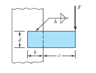
9–17 to 9–20 A steel bar of thickness h, to be used as a beam, is welded to a vertical support by two fillet welds as shown in the figure.
- (a) Find the safe bending force F if the allowable shear stress in the welds is τallow.
- (b) In part a, you found a simple expression for F in terms of the allowable shear stress. Find the allowable load if the electrode is E7010, the bar is hot-rolled 1020, and the support is hot-rolled 1015.
| Problem Number | b | c | d | h | τallow |
| 9–17 | 50 mm | 150 mm | 50 mm | 5 mm | 140 MPa |
| 9–18 | 2 in | 6 in | 2 in |
|
25 kpsi |
| 9–19 | 50 mm | 150 mm | 30 mm | 5 mm | 140 MPa |
| 9–20 | 4 in | 6 in | 2 in |
|
25 kpsi |
Expert Solution & Answer
Want to see the full answer?
Check out a sample textbook solution
Students have asked these similar questions
A beam is supported and loaded as shown in the figure. Data: L = 1000 mm, c = 300 mm, f = 100 mm, D = 100 mm, d = 80 mm.
The beam consists of different parts that are welded, and the fillet weld size a is 4 mm. The load q is 2 kN/m, and P = 10 kN.
Calculate the maximum stress in the welds.
appropriate length of the weld joint shown in the figure if the force is equal to (60000lb) and the operating stress value is (60ksi) and the size of the weld is (1/4in).
(1) What are the methods used to obtain a good weld when welding steel when the carbon content is high? b) Find the appropriate size and length for the weld joint shown in the figure if the strength is equal to (70000Ib) and the allowable shear stress value is 40ksi and the weld rib dimension is (1/4in)
Chapter 9 Solutions
SHIGLEY'S MECH.ENGIN....(LOOSE)>CUSTOM<
Ch. 9 - 91 to 94 The figure shows a horizontal steel bar...Ch. 9 - 91 to 94 The figure shows a horizontal steel bar...Ch. 9 - 91 to 94 The figure shows a horizontal steel bar...Ch. 9 - 91 to 94 The figure shows a horizontal steel bar...Ch. 9 - 95 to 98 For the weldments of Probs. 91 to 94, the...Ch. 9 - 95 to 98 For the weldments of Probs. 91 to 94, the...Ch. 9 - 95 to 98 For the weldments of Probs. 91 to 94, the...Ch. 9 - 95 to 98 For the weldments of Probs. 91 to 94, the...Ch. 9 - 99 to 912 The materials for the members being...Ch. 9 - Prob. 10P
Ch. 9 - Prob. 11PCh. 9 - 99 to 912 The materials for the members being...Ch. 9 - 913 to 916 A steel bar of thickness h is welded to...Ch. 9 - 913 to 916 A steel bar of thickness h is welded to...Ch. 9 - 913 to 916 A steel bar of thickness h is welded to...Ch. 9 - Prob. 16PCh. 9 - Prob. 17PCh. 9 - 917 to 920 A steel bar of thickness h, to be used...Ch. 9 - 917 to 920 A steel bar of thickness h, to be used...Ch. 9 - 917 to 920 A steel bar of thickness h, to be used...Ch. 9 - Prob. 21PCh. 9 - 921 to 924 The figure shows a weldment just like...Ch. 9 - Prob. 23PCh. 9 - Prob. 24PCh. 9 - 9-25 to 9-28 The weldment shown in the figure is...Ch. 9 - 9-25 to 9-28 The weldment shown in the figure is...Ch. 9 - Prob. 27PCh. 9 - 925 to 928 The weldment shown in the figure is...Ch. 9 - The permissible shear stress for the weldment...Ch. 9 - Prob. 30PCh. 9 - 9-30 to 9-31 A steel bar of thickness h is...Ch. 9 - In the design of weldments in torsion it is...Ch. 9 - Prob. 33PCh. 9 - Prob. 34PCh. 9 - The attachment shown carries a static bending load...Ch. 9 - The attachment in Prob. 935 has not had its length...Ch. 9 - Prob. 37PCh. 9 - Prob. 39PCh. 9 - Prob. 40PCh. 9 - Prob. 42PCh. 9 - 9-43 to 9-45 A 2-in dia. steel bar is subjected to...Ch. 9 - 9-43 to 9-45 A 2-in dia. steel bar is subjected to...Ch. 9 - Prob. 45PCh. 9 - Prob. 46PCh. 9 - Find the maximum shear stress in the throat of the...Ch. 9 - The figure shows a welded steel bracket loaded by...Ch. 9 - Prob. 49PCh. 9 - Prob. 50PCh. 9 - Prob. 51PCh. 9 - Brackets, such as the one shown, are used in...Ch. 9 - For the sake of perspective it is always useful to...Ch. 9 - Hardware stores often sell plastic hooks that can...Ch. 9 - For a balanced double-lap joint cured at room...
Knowledge Booster


Learn more about
Need a deep-dive on the concept behind this application? Look no further. Learn more about this topic, mechanical-engineering and related others by exploring similar questions and additional content below.Similar questions
- : A cylindrical tank with diameter d = 18 in, is subjected to internal gas pressure p = 450 psi. The tank is constructed of steel sections that arc welded circum fereiitially (sec figure). The heads of the tank are hemispherical. The allowable tensile and shear stresses are 8200 psi and 3000 psi, respectively. Also, the allowable tensile stress perpendicular to a weld is 6250 psi. Determine the minimum required thickness /minof (a) the cylindrical part of the tank and (b) the hemispherical heads.arrow_forwardA welded joint, as shown in figure below, is subjected to an eccentric load of 2500 N. Find thesize of the weld, if the maximum shear stress in the weld is not to exceed 50 N/mm2arrow_forwardAll-round fillet weld with a steel beam weld thickness a=6 mm and weld seam length shown in the figure welded to the steel column. Forces of 2 kN and 3 kN from the beam end in the horizontal and vertical directions, respectively has been applied. The smallest yield strength of the weld material so that the steel structure has a safety of 2.5. Calculate according to von Mises static damage theory ?arrow_forward
- The carrier plate material St52 (S355) given in the figure below is welded to the body. combined. F1 = 4 kN and F2 = 40 kN static forces act on the plate. Source I. Quality (v2 = 1), no impact (v3 = 1), weld thickness a = 5 mm, safety coefficient s = 2 and weld seam coefficient v1 = 0.8 will be taken. Find out whether a = 5 mm weld seam thickness is sufficient or not, according to the data in the figure and above.arrow_forwardA tie-down on the deck of a sailboat consists of a bent bar boiled at both ends, as shown in the figure. The diameter dBof the bar is 1/4 in., the diameter D Wof the washers is 7/8 in., and the thickness is of the fiberglass deck is 3/8 in. If the allowable shear stress in the fiberglass is 300 psi, and the allowable bearing pressure between the washer and the fiberglass is 550 psi, what is the allowable load P allowon the tie-down?arrow_forwardA 1/4 in fillet weld is to transmit a total force of 12,000 lb. If the allowable unit stress in shear on the weld is 15,800 psi, the minimum effective length of the weld must be A. 5.4 B 4.9 in C. 4.3 in D 3.9 in.arrow_forward
- The figure shows a solid 2-inch diameter roller that is attached to the wall by means of a permanent clamping. Specify the weld size for the case where the maximum allowable shear stress is 18 kpsi.arrow_forwardThe arm in the figure is combined with a rod with a diameter of d=30 mm and a neck (corner) weld of a=5 mm thickness to the rod wall sourced with. The force acting on the arm is F=2 kN. The lengths are L1=L2=100 mm. Joined parts St37-2 (ak=235 N/mm2 ) made of material. Welding is I. Quality and has no impact effect. Check if the source in zone A is safe. Please pay. (S=1.5 V1=0.8)arrow_forwardThe arm in the figure is combined with a rod with a diameter of d=30 mm and a neck (corner) weld with a thickness of a= 5mm to the rod wall.sourced with. The force acting on the arm is F=2 kN. The lengths are L1=L2=100 mm. Joined parts are made of St37-2 (ak=235 N/mm2) material. Welding is I. Quality and has no impact effect. Check if the source in zone A is safe. (S=1.5 V1=0.8)arrow_forward
- A bracket is as shown in figure 2. Determine the uniform weld size for the arrangement. The permissible shear stress of weld material is 80 MPa. Consider the loading condition as shown in figure.arrow_forwardIn the figure shown, the cutaway view shows a solid aluminum alloy of L= 600mm, A= 707mm^2 and E= 70GPa rod within a closed-end bronze of L= 610mm, A= 1206mm^2 and E= 100GPa tube. Before the load P is applied, there is a clearance of 2mm between the rod flange at B and the tube closure at A. After load P is applied, the solid aluminum alloy rod stretches enough so that flange B contacts the closed end of the tube at A. If the load applied to the lower end of the aluminum rod is P= 345KN, calculate:A. The normal stress in bronze tube, in MPa.B. The elongation of bronze tube, in mm.arrow_forwardA plate 100 mm wide and 12.5 mm thick is to be welded to another plate by means of parallel fillet welds. The plates are subjected to a load of 50 kN. Find the length of the weld so that the maximum stress does not exceed 56 MPa. Consider the joint first under static loading and then under fatigue loading.arrow_forward
arrow_back_ios
SEE MORE QUESTIONS
arrow_forward_ios
Recommended textbooks for you
 Mechanics of Materials (MindTap Course List)Mechanical EngineeringISBN:9781337093347Author:Barry J. Goodno, James M. GerePublisher:Cengage Learning
Mechanics of Materials (MindTap Course List)
Mechanical Engineering
ISBN:9781337093347
Author:Barry J. Goodno, James M. Gere
Publisher:Cengage Learning
Differences between Temporary Joining and Permanent Joining.; Author: Academic Gain Tutorials;https://www.youtube.com/watch?v=PTr8QZhgXyg;License: Standard Youtube License